Nissan Sentra Service Manual: Power supply and ground circuit
Bcm (body control system) (with intelligent key system)
BCM (BODY CONTROL SYSTEM) (WITH INTELLIGENT KEY SYSTEM) : Diagnosis Procedure
Regarding Wiring Diagram information, refer to BCS-51, "Wiring Diagram".
1.CHECK FUSES AND FUSIBLE LINK
Check that the following fuses and fusible link are not blown.
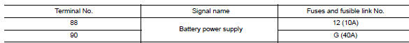
Is the fuse blown? YES >> Replace the blown fuse or fusible link after repairing the affected circuit.
NO >> GO TO 2.
2.Check power supply circuit
- Disconnect BCM connector M85.
- Check voltage between BCM connector M85 and ground.
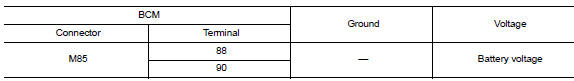
Is the inspection result normal? Yes >> go to 3.
No >> repair harness or connector.
3.Check ground circuit
Check continuity between bcm connector m85 and ground.
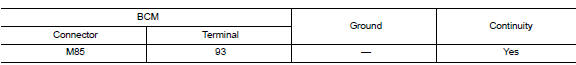
Is the inspection result normal? YES >> Inspection End.
NO >> Repair harness or connector.
Bcm (body control system) (without intelligent key system)
BCM (BODY CONTROL SYSTEM) (WITHOUT INTELLIGENT KEY SYSTEM) : Diagnosis Procedure
Regarding Wiring Diagram information, refer to BCS-111, "Wiring Diagram".
1.Check fuses and fusible link
Check that the following fuses and fusible link are not blown.
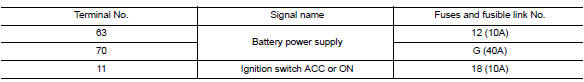
Is the fuse blown? Yes >> replace the blown fuse or fusible link after repairing the affected circuit.
No >> go to 2.
2.Check power supply circuit
- Turn ignition switch OFF.
- Disconnect bcm connectors.
- Check voltage between bcm connector and ground.
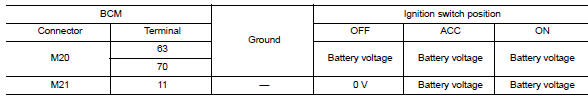
Is the inspection result normal? YES >> GO TO 3.
NO >> Repair harness or connector.
Is the inspection result normal? Yes >> go to 3.
No >> repair harness or connector.
3.Check ground circuit
Check continuity between bcm connector and ground.
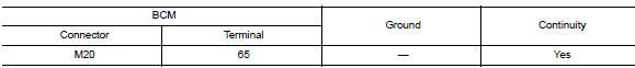
Is the inspection result normal? YES >> Inspection End.
NO >> Repair harness or connector.

 Battery saver output/power supply circuit
Description
Provides the battery saver output/power supply. Also cuts the power supply
when the interior lamp battery
saver is activated.
Component function check
1.Check battery saver output/po ...
Other materials:
Fuel (Regular Unleaded Gasoline Recommended)
Use unleaded regular gasoline with an octane rating of at least 87 AKI
(Anti-Knock Index) number (Research
octane number 91). E-85 fuel (85% fuel ethanol, 15% unleaded gasoline) may only
be used in vehicles specifically
designed for E-85 fuel (i.e. Flexible Fuel Vehicle - FFV models).
CAUTION ...
How to Follow Test Groups in Trouble Diagnosis
Test group number and test group title
Test group number and test group title are shown in the upper portion of
each test group.
Work and diagnosis procedure
Start to diagnose a problem using procedures indicated in enclosed test
groups.
Questions and results
...
Bluetooth® Hands-Free Phone System with
Navigation System (if so equipped)
WARNING
Use a phone after stopping your vehicle
in a safe location. If you have to use a
phone while driving, exercise extreme
caution at all times so full attention may
be given to vehicle operation.
If you are unable to devote full attention
to vehicle operation ...
