Nissan Sentra Service Manual: Power supply and ground circuit
A/C AUTO AMP
A/C AUTO AMP. : Diagnosis Procedure
Regarding Wiring Diagram information, refer to HAC-41, "Wiring Diagram".
1.CHECK FUSE
Check fuses [No. 5, 8 and 21, located in the fuse block (J/B)].
NOTE:
Refer to PG-47, "Terminal Arrangement".
Is the inspection result normal? YES >> GO TO 2.
NO >> Replace the blown fuse after repairing the affected circuit.
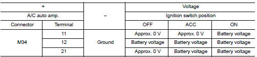
2.Check A/C auto amp. Power supply
- Turn ignition switch OFF.
- Disconnect A/C auto amp. connector.
- Check voltage between A/C auto amp. harness connector and ground.
Is the inspection result normal? YES >> GO TO 3.
NO >> Repair harness or connector between A/C auto amp. and fuse block (J/B).
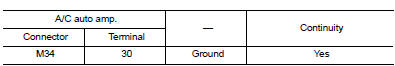
3.Check A/Cauto amp. Ground circuit
- Turn ignition switch OFF
- Check continuity between A/C auto amp. harness connector and ground.
Is the inspection result normal? YES >> Inspection End.
NO >> Repair harness or connector.
A/C SWITCH ASSEMBLY
A/C SWITCH ASSEMBLY : Component Function Check
1.CHECK OPERATION
- Press the AUTO switch, and then check that “AUTO” is shown on the display.
- Operate the temperature control switch (driver side). Check that the fan speed or outlet changes. (The discharge air temperature or fan speed varies depending on the ambient temperature, in-vehicle temperature, and temperature setting.)
Does it operate normally? YES >> Inspection End.
NO >> Perform trouble diagnosis for the A/C switch assembly. Refer to HAC-84, "A/C SWITCH ASSEMBLY : Diagnosis Procedure".
A/C SWITCH ASSEMBLY : Diagnosis Procedure
Regarding Wiring Diagram information, refer to HAC-41, "Wiring Diagram".
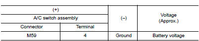
1.Check A/C Switch assembly power supply
- Disconnect the A/C switch assembly connector.
- Turn ignition switch ON.
- Check voltage between A/C switch assembly harness connector and ground.
Is the inspection result normal? YES >> GO TO 3.
NO >> GO TO 2.
2.Check fuse
Check 10A fuse [No.5, located in the fuse block (J/B)].
NOTE:
Refer to PG-47, "Terminal Arrangement".
Is the inspection result normal? YES >> Check harness for open circuit. Repair or replace if necessary.
NO >> Check harness for short circuit. Repair or replace if necessary.
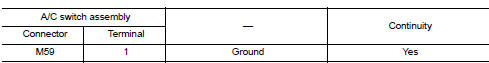
3.Check A/C switch assembly ground circuit
- Turn ignition switch OFF.
- Check continuity between A/C switch assembly harness connector and ground.
Is the inspection result normal? YES >> Replace the A/C switch assembly. Refer to HAC-104, "Removal and Installation".
NO >> Repair the harnesses or connectors.
A/C SWITCH ASSEMBLY SIGNAL CIRCUIT
Diagnosis Procedure
Regarding Wiring Diagram information, refer to HAC-41, "Wiring Diagram".
1.CHECK WITH SELF-DIAGNOSIS FUNCTION OF CONSULT
- Using CONSULT, perform “SELF-DIAGNOSIS RESULTS” of HVAC.
- Check if any DTC No. is displayed in the self-diagnosis results.
NOTE:
If DTC is displayed along with DTC U1000 or U1010, first diagnose the DTC U1000 or U1010. Refer to HAC- 58, "DTC Logic" (U1000) or HAC-59, "DTC Logic" (U1010).
Is any DTC No. displayed? YES >> Perform diagnosis for the applicable DTC. Refer to HAC-38, "DTC Index".
NO >> GO TO 2.
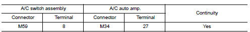
2.Check RX (A/C Switch assembly → A/C Auto AMP) Circuit continuity
- Turn ignition switch OFF.
- Disconnect the A/C switch assembly and the A/C auto amp. connectors.
- Check continuity between A/C switch assembly harness connector and A/C auto amp. harness connector.
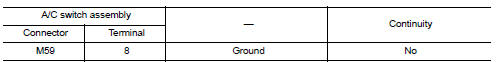
- Check continuity between A/C switch assembly harness connector M79 terminal 10 and ground.
Is the inspection result normal? YES >> GO TO 3.
NO >> Repair harness or connector.
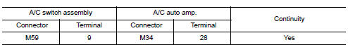
3.Check TX(A/C auto amp. ?¨ A/C switch assembly) circuit continuity
- Check continuity between A/C switch assembly harness connector and A/C auto amp. harness connector.
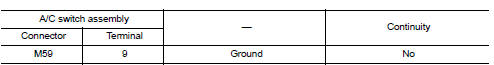
- Check continuity between A/C switch assembly harness connector M79 terminal 9 and ground.
Is the inspection result normal? YES >> Perform trouble diagnosis for the A/C switch assembly. Refer to HAC-84, "A/C SWITCH ASSEMBLY : Diagnosis Procedure".
NO >> Repair harness or connector.
A/C ON SIGNAL
Component Function Check
1.Check A/C On signal
 With CONSULT
- Turn ignition switch ON.
- Operate blower motor.
- Select “AIR CONDITIONER” of “BCM” using CONSULT
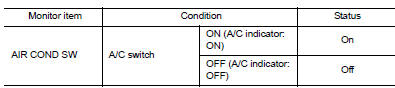
- Select “AIR COND SW” in “DATA MONITOR” mode.
- Check A/C ON signal when the A/C switch is operated.
Is the inspection result normal? YES >> Inspection End.
NO >> Refer to HAC-86, "Diagnosis Procedure".
Diagnosis Procedure
Regarding Wiring Diagram information, refer to HAC-41, "Wiring Diagram".
1.CHECK A/C ON SIGNAL
- Turn ignition switch OFF.
- Disconnect A/C auto amp. connector.
- Turn ignition switch ON.
- Check output waveform between A/C auto amp. harness connector and ground with using oscilloscope.
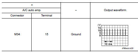
Is the inspection result normal? YES >> Replace A/C auto amp. Refer to HAC-105, "Removal and Installation".
NO >> GO TO 2.
2.Check A/C On signal circuit for open
- Turn ignition switch OFF.
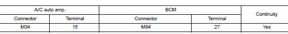
- Disconnect BCM connector.
- Check continuity between A/C auto amp. harness connector and BCM harness connector.
Is the inspection result normal? YES >> GO TO 3.
NO >> Repair harness or connector.
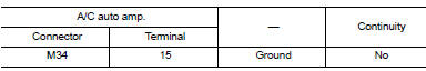
3.Check A/C On signal circuit for short
Check continuity between A/C auto amp. harness connector and ground.
Is the inspection result normal? YES >> Replace BCM. Refer to BCS-73, "Removal and Installation".
NO >> Repair harness or connector.
BLOWER FAN ON SIGNAL
Component Function Check
1.Check blower fan on signal
 With CONSULT
- Turn ignition switch ON.
- Select “AIR CONDITIONER” of “BCM” using CONSULT.
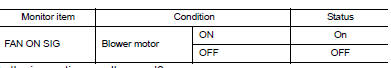
- Select “FAN ON SIG” in “DATA MONITOR” mode.
- Check blower fan ON signal when the fan control dial is operated.
Is the inspection result normal? YES >> Inspection End.
NO >> Refer to HAC-88, "Diagnosis Procedure".
Diagnosis Procedure
Regarding Wiring Diagram information, refer to HAC-41, "Wiring Diagram".
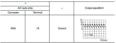
1.Check blower fan on signal
- Turn ignition switch OFF.
- Disconnect A/C auto amp. harness connector.
- Turn ignition switch ON.
- Check output waveform between A/C auto amp. and ground with using oscilloscope.
Is the inspection result normal? YES >> Replace A/C auto amp. Refer to HAC-105, "Removal and Installation".
NO >> GO TO 2.
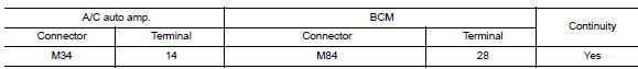
2.Check blower fan on signal circuit for open
- Turn ignition switch OFF
- Disconnect BCM connector
- Check continuity A/C auto amp. harness connector and BCM harness connector.
Is the inspection result normal?
YES >> GO TO 3.
NO >> Repair harness or connector.
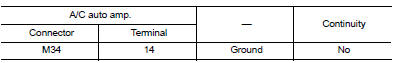
3.Check blower fan on signal circuit for short
Check continuity between A/C auto amp. harness connector and ground.
Is the inspection result normal? YES >> Replace BCM. Refer to BCS-73, "Removal and Installation".
NO >> Repair harness or connector.
BLOWER MOTOR
Diagnosis Procedure
Regarding Wiring Diagram information, refer to HAC-41, "Wiring Diagram".
1.CHECK FUSE
- Turn ignition switch OFF.
- Check following fuses.
- 10A fuse [No. 21, located in fuse block (J/B)]
- 15A fuses [Nos. 20 and 22, located in fuse block (J/B)]
NOTE:
Refer to PG-47, "Terminal Arrangement".
Is the inspection result normal? YES >> GO TO 2.
NO >> Replace the blown fuse after repairing the affected circuit.
2.Check blower motor power supply
- Disconnect blower motor connector.
- Turn ignition switch ON.
- Check voltage between blower motor harness connector and ground.

Is the inspection result normal? YES >> GO TO 4.
NO >> GO TO 3.
3.CHECK BLOWER RELAY
- Turn ignition switch OFF.
- Check blower relay. Refer to HAC-93, "Component Inspection (Blower Motor Relay)".
Is the inspection result normal? YES >> Repair harness or connector between blower motor and fuse.
NO >> Replace blower relay.
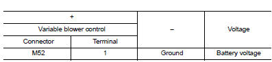
4.Check blower motor control circuit
- Turn ignition switch OFF.
- Connect blower motor connector.
- Disconnect variable blower control connector.
- Turn ignition switch ON.
- Check voltage between variable blower control harness connector and ground.
Is the inspection result normal? YES >> GO TO 6.
NO >> GO TO 5.
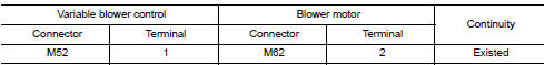
5.Check blower motor control circuit for open
- Turn ignition switch OFF.
- Disconnect blower motor connector.
- Check continuity between variable blower control harness connector and blower motor harness connector.
Is the inspection result normal? YES >> Replace blower motor. Refer to VTL-10, "Removal and Installation".
NO >> Repair harness or connector.
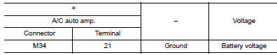
6.Check A/C Auto amp. Ignition power supply
- Turn ignition switch OFF.
- Disconnect A/C auto amp.
- Turn ignition switch ON.
- Check voltage between A/C auto amp. harness connector and ground.
Is the inspection result normal? YES >> GO TO 7.
NO >> Repair harness or connector between A/C auto amp. and fuse.
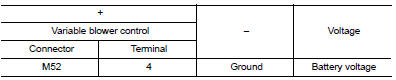
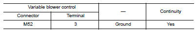
7.Check variable blower control ignition power supply
Check voltage between variable blower control harness connector and ground.
Is the inspection result normal? YES >> GO TO 8.
NO >> Repair harness or connector between variable blower control and fuse.
8.Check variable blower control ground circuit for open
-
Turn ignition switch OFF.
-
Check continuity between variable blower control harness connector and ground.
Is the inspection result normal? YES >> GO TO 9.
NO >> Repair harness or connector.
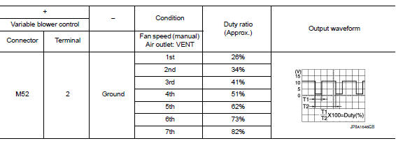
9.Check variable blower control control signal
-
Connect variable blower control connector and A/C auto amp. connector.
-
Turn ignition switch ON.
-
Set air outlet to VENT.
-
Change fan speed from 1st – 7th, and check duty ratios between variable blower control harness connector and ground by using an oscilloscope.
NOTE:
Calculate the drive signal duty ratio as shown in the figure.
T2 = Approx. 1.6 ms
Is the inspection result normal? Yes >> replace variable blower control. Refer to hac-113, "removal and installation".
No >> go to 10.
10.Check variable blower control control signal circuit for open
-
Turn ignition switch off.
-
Disconnect variable blower control connector and a/c auto amp. Connector.
-
Check continuity between variable blower control harness connector and A/C auto amp. harness connector.
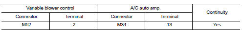
Is the inspection result normal? YES >> GO TO 11.
NO >> Repair harness or connector.
11.Check variable blower control control signal circuit for short
Check continuity between variable blower control harness connector and ground.
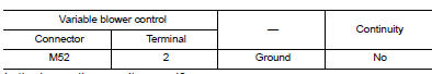
Is the inspection result normal? Yes >> replace a/c auto amp. Refer to hac-105, "removal and installation".
No >> repair harness or connector.
Component Inspection (Blower Motor)
1.Check blower motor
- Connect battery voltage to terminal 1 of blower motor.
- Connect ground to terminal 2 of blower motor.
Does the blower fan operate? YES >> Intermittent incident. Refer to GI-39, "Intermittent Incident".
NO >> Replace blower motor. Refer to VTL-10, "Removal and Installation".
Component Inspection (Blower Motor Relay)
1.Check blower relay
- Turn ignition switch off.
- Remove blower motor relay.
- Check continuity between blower motor relay terminals 3 and 5 when voltage is supplied between terminals 1 and 2.
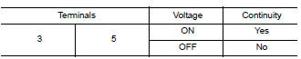
Is the inspection result normal? Yes >> inspection end.
No >> replace blower motor relay.
MAGNET CLUTCH
Component Function Check
1.Check magnet clutch operation
Perform auto active test of ipdm e/r. Refer to pcs-9, "diagnosis description".
Does it operate normally? Yes >> inspection end.
No >> refer to hac-94, "diagnosis procedure".
Diagnosis Procedure
Regarding wiring diagram information, refer to hac-41, "wiring diagram".
1.Check fuse
- Turn ignition switch off.
- Check 10A fuse (No. 39, located in IPDM E/R).
Note:
Refer to PG-49, "IPDM E/R Terminal Arrangement".
Is the inspection result normal? Yes >> go to 2.
No >> replace the blown fuse after repairing the affected circuit.
2.Check magnet clutch power supply circuit
- Disconnect compressor connector and IPDM E/R connector.
- Check continuity between compressor harness connector and ipdm e/r harness connector.
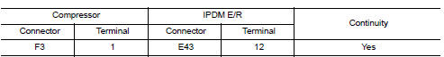
Is the inspection result normal? Yes >> go to 3.
No >> repair harness or connector.
3.Check magnet clutch ground circuit
- Disconnect compressor connector.
- Check continuity between compressor harness connector and ground.
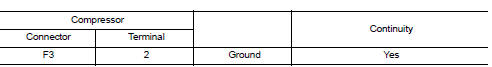
Is the inspection result normal? Yes >> go to 4.
No >> repair harness or connector.
4.Check magnet clutch
Directly apply battery voltage to the magnet clutch. Check operation visually and by sound.
Does it operate normally? Yes >> replace ipdm e/r. Refer to pcs-30, "removal and installation".
No >> replace magnet clutch. Refer to ha-31, "magnet clutch : removal and installation".
ECV (ELECTRICAL CONTROL VALVE)
Diagnosis Procedure
Regarding wiring diagram information, refer to hac-41, "wiring diagram".
1.Check ECV (electrical control valve) power supply
- Turn ignition switch off.
- Disconnect compressor connector
- Turn ignition switch ON.
- Check voltage between compressor harness connector and ground.
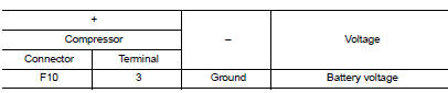
Is the inspection result normal? Yes >> go to 3.
No >> go to 2.
2.Check fuse
- Turn ignition switch off.
- Check 10 A fuse [No. 5, located in fuse block (J/B)]. Refer to PG-47, "Terminal Arrangement"
Is the inspection result normal? Yes >> repair harness or connector.
No >> replace the blown fuse after repairing the affected circuit.
3.Check ecv control signal circuit for open
- Turn ignition switch OFF.
- Disconnect a/c auto amp. Connector.
- Check continuity between compressor harness connector and a/c auto amp. Harness connector.
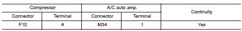
Is the inspection result normal? Yes >> go to 4.
No >> repair harness or connector.
4.Check ecv control signal circuit for short
Check continuity between compressor harness connector and ground.
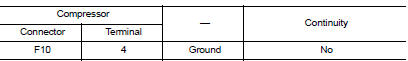
Is the inspection result normal? Yes >> go to 5.
No >> repair harness or connector.
5.Check ECV
Check ecv. Refer to hac-96, "component inspection".
Is the inspection result normal? YES >> GO TO 6.
NO >> Replace compressor. Refer to HA-31, "COMPRESSOR : Removal and Installation".
6.Check intermittent incident
Refer to GI-39, "Intermittent Incident".
Is the inspection result normal? YES >> Replace A/C auto amp. Refer to HAC-105, "Removal and Installation".
NO >> Repair or replace malfunctioning parts.
Component Inspection
1.Check ECV (electrical control valve)
- Turn ignition switch off.
- Disconnect compressor connector.
- Check continuity between compressor connector F10 terminals.
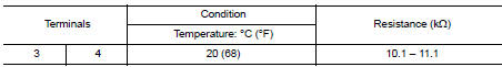
Is the inspection result normal? YES >> Inspection End.
NO >> Replace compressor. Refer to HA-31, "COMPRESSOR : Removal and Installation".
 DTC/circuit diagnosis
U1000 CAN COMM CIRCUIT
Description
CAN (Controller Area Network) is a serial communication system for real time
application. It is an on-vehicle
multiplex communication system with high data com ...
 Symptom diagnosis
HEATER AND AIR CONDITIONING SYSTEM
CONTROL SYMPTOMS
Diagnosis Chart By Symptom
Note:
Perform the self-diagnoses with consult before performing the symptom
diagnosis. If dtc is detected, perform
...
Other materials:
Periodic maintenance
Introduction of periodic maintenance
The following tables show the normal maintenance schedule. Depending upon
weather and atmospheric conditions,
varying road surfaces, individual driving habits and vehicle usage, additional
or more frequent maintenance
may be required.
Periodic maintenan ...
Low tire pressure warning lamp does not turn oFF
Low Tire Pressure Warning Lamp Stays On When Ignition Switch Is Turned On
DIAGNOSTIC PROCEDURE
1.INSPECT BCM CONNECTOR
Turn ignition switch OFF.
Disconnect BCM connectors.
Check terminals for damage or loose connections.
Is the inspection result normal?
YES >> GO TO 2.
NO > ...
Continuously Variable Transmission (CVT) (if so equipped)
The ignition lock is designed so that the ignition
switch cannot be turned to the LOCK position
until the shift lever is moved to the P (Park)
position.
When moving the ignition switch to the
LOCK position, make sure the shift lever is in
the P (Park) position.
When removing the key ...
