Nissan Sentra Service Manual: Instrument panel assembly
Exploded View
- Instrument panel assembly
- Ambient sensor
- Defroster grille (RH)
- Defroster grille (LH)
- Sunload sensor (if equipped)
- Side defroster grille (LH)
- Instrument side finisher (LH)
- Side ventilator grille (LH)
- Steering column upper cover
- Combination switch
- Steering column lower cover
- Instrument finisher (LH)
- Combination meter
- Switch carrier
- Instrument lower panel LH
- Cluster lid A
- Instrument finisher B
- Center ventilator grille assembly
- Cluster lid C
- Hazard switch
- AV control unit
- Cluster lid C lower
- A/C switch assembly
- Glove box lid
- Glove box mat
- Glove box assembly
- Side ventilator grille (RH)
- Instrument side finisher (RH)
- Side defroster grille (RH)
Removal and Installation
CAUTION:
- Be careful not to scratch instrument panel pad and other parts.
- Before servicing, turn ignition switch OFF, disconnect both battery terminals and wait at least three minutes.
REMOVAL
- Disconnect the negative and positive battery terminals, then wait at least three minutes. Refer to PG-50, "Removal and Installation (Battery)".
- Remove the instrument side finishers (1) (LH/RH) using a suitable tool.
NOTE:
LH side shown; RH side similar.
- Remove the front pillar finishers (LH/RH). Refer to INT-24, "FRONT PILLAR FINISHER : Removal and Installation".
- Remove the front kicking plates (LH/RH). Refer to INT-24, "KICKING PLATE INNER : Removal and Installation".
- Remove the instrument lower panel LH. Refer to IP-21, "Removal and Installation".
- Remove the audio unit. Refer to AV-58, "Removal and Installation" (BASE AUDIO), AV-122, "Removal and Installation" (DISPLAY AUDIO WITHOUT BOSE) or AV-203, "Removal and Installation" (DISPLAY AUDIO WITH BOSE).
- Remove the AV control unit. Refer to AV-298, "Removal and Installation" (NAVIGATION WITHOUT BOSE) or AV-406, "Removal and Installation" (NAVIGATION WITH BOSE).
- Remove the steering wheel. Refer to ST-10, "Removal and Installation".
- Remove the combination switch. Refer to BCS-75, "Removal and Installation".
- Remove the combination meter. Refer to MWI-77, "Removal and Installation".
- Remove the glove box assembly. Refer to IP-22, "Removal and Installation".
- Remove the center console assembly. Refer to IP-17, "Removal and Installation".
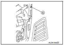
- Remove the instrument panel screws (A) (LH/RH).
NOTE:
The instrument panel screws (A) can be found near the side defroster grilles (LH/RH).
- Remove the remaining instrument panel screws.
- Disconnect the harness connector from the front passenger air bag module.
- Disconnect all remaining harness connectors.
- With the help of an assistant, remove the instrument panel assembly.
CAUTION:
Be careful not to scratch the instrument panel pad and other parts.
INSTALLATION
Installation is in the reverse order of removal.
- If replacing the instrument panel, transfer all the necessary parts to the new instrument panel.

 Steering column covers
Removal and Installation
REMOVAL
Remove the steering column cover screws (A), then remove the
steering column upper (1) and lower (2) covers.
NOTE:
Shown with steering wheel removed for ...
Other materials:
FM/AM radio with compact disc (CD) player (if so equipped)
CD eject button
CD insert slot
SCAN button
DISP button
RPT/RDM button
TUNE/FOLDER knob / MENU button
AUX IN jack
AUX button
CD button
AM button
FM button
VOL (volume) control knob
/ (power) button
Station select (1 - 6) buttons
TRACK button
SEEK button
For ...
Normal operating condition
Compass
Compass : description
Compass
The electronic compass is highly protected from changes in most magnetic
fields. However, some large
changes in magnetic fields can affect it. Some examples are (but not limited
to): high tension power lines,
large steel buildings, subways, steel ...
DTC/circuit diagnosis
U1000 CAN COMM CIRCUIT
Description
CAN (Controller Area Network) is a serial communication system for real time
application. It is an on-vehicle
multiplex communication system with high data communication speed and excellent
error detection ability.
Many electronic control units are equip ...
