Nissan Sentra B18 (2020-2025) Service Manual: Heated Steering Wheel System
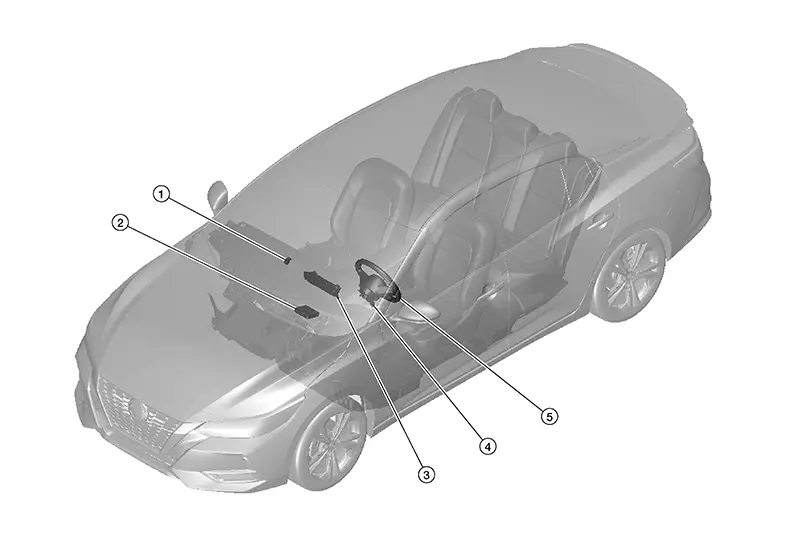
Component Parts Location
|
No. |
Component |
Function |
|---|---|---|
|
1. |
Heated steering wheel relay |
Refer to Heated Steering Wheel Relay. |
|
2. |
A/C auto amp. |
Refer to A/C Auto Amp. |
|
3. |
A/C switch assembly (heated steering wheel switch) |
The heated steering wheel switch is integrated into the A/C switch assembly and is used to activate/deactivate the heated steering wheel system. Refer to Component Parts Location for detailed component location. |
|
4. |
Combination switch (spiral cable) |
The spiral cable provides a rotating physical connection to the steering wheel. Refer to Component Parts Location for detailed component location. |
|
5. |
Heated steering wheel |
Refer to Heated Steering Wheel. |
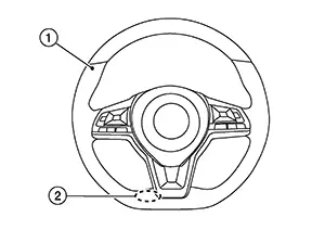
Heated Steering Wheel
With the power supply from the heated steering wheel relay, the heated steering wheel controls temperature through the heating element 1 and thermostat 2 built into the steering wheel.
-
Heating element: Generates heat by energization.
Note:
Heating element is located at the back of the steering wheel leather surface.
-
Thermostat: Turns ON/OFF power supply according to the specified temperature.
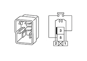
Heated Steering Wheel Relay
Through the control of the A/C auto amp., the heated steering wheel relay turns ON/OFF electricity to the heating element built-in the steering wheel. For location, refer to Component Parts Location.
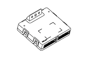
A/c Auto Amp.
-
Located behind front side of center console.
-
A/C auto amp. turns ON/OFF the heated steering wheel relay, according to the heated steering wheel switch signal transmitted from the A/C switch assembly via LIN communication.
-
The A/C auto amp. includes a timer. The heated steering wheel relay is turned OFF when the timer operating time reaches 30 minutes.
-
Timer: Turns ON/OFF the heated steering wheel relay for a specified period of time.
-
-
For other information of A/C auto amp., refer to A/C Auto Amp.
Heated Steering Wheel Switch
-
The heated steering switch is integrated in the A/C switch assembly and is used to activate heated steering wheel.
-
The A/C switch assembly transmits the heated steering wheel switch signal to the A/C auto amp. via LIN communication.
 Component Parts
...
 System
...
Other materials:
Symptom Table
Symptom Table
Symptom
Reference
No normal cranking
Refer to Work Flow (With 165-DSS–5000P) or Work Flow (Without
165-DSS ...
Air conditioning cut control
AIR CONDITIONING CUT CONTROL : System Description
SYSTEM DIAGRAM
INPUT/OUTPUT SIGNAL CHART
Sensor
Input Signal to ECM
ECM function
Actuator
Crankshaft position sensor (POS)
Engine speed*
Piston position
Air conditioner
cut control
IPDM E/R
↓Air ...
System Description
System Description
SYSTEM DIAGRAM
Component
Function
Trunk lid opener switch
Transmit trunk lid open switch
signal to ...
