Nissan Sentra Service Manual: ECU diagnosis information
EPS control unit
Reference Value
VALUES ON THE DIAGNOSIS TOOL
The following table includes information (items) inapplicable to this vehicle. For information (items) applicable to this vehicle, refer to CONSULT display items.
CAUTION:
The output signal indicates the EPS control unit calculation data. The normal values will be displayed even in the event that the output circuit (harness) is open.
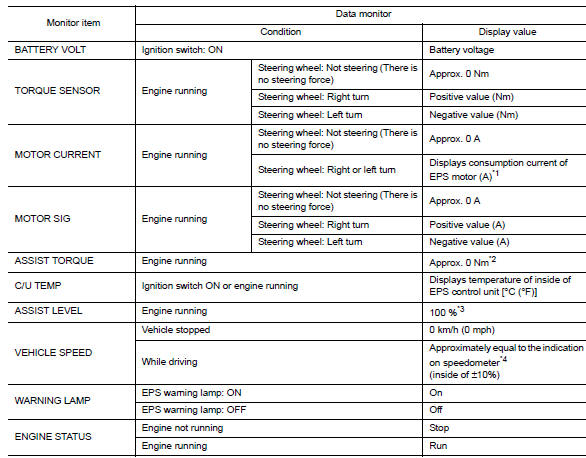
*1: Almost in accordance with the value of “MOTOR SIG”. It is not a malfunction though these values are not accorded when steering quickly.
*2: A fixed value is indicated regardless of steering turning.
*3: Normally displays 100%. In case of an excessive stationary steering, the assist curvature gradually falls.
However, it returns to 100% when left standing.
*4: It is not a malfunction, though it might not be corresponding just after ignition switch in turned ON.
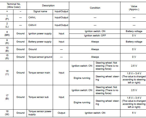
Terminal layout
Physical values
Fail-Safe
-
If any malfunction occurs in the system and control unit detects the malfunction, eps warning lamp on combination meter turns on to indicate system malfunction.
-
When eps warning lamp is on, the system enters into a manual steering state. (Control turning force steering wheel becomes heavy.)
-
Under abnormal vehicle speed signal conditions, vehicle speed is judged as constant.
Protection Function
Eps control unit decreases the output signal to eps motor while extremely using the power steering function (e.G., Full steering) consecutively for protecting eps motor and eps control unit (overload protection control).
While activating overload protection control, the assist torque gradually decreases, and the steering wheel Turning force becomes heavy. The normal assist torque is recovered if the steering wheel is not turned for a while.
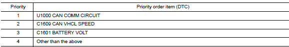
DTC Inspection Priority Chart
When multiple dtcs are detected simultaneously, check one by one depending on the following priority list.
DTC Index
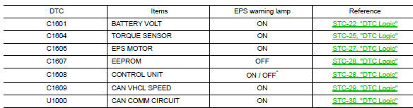
*: Even if dtc is detected, eps warning lamp does not turn on when assist torque is generated.
 Diagnosis system (EPS control unit)
CONSULT Function
FUNCTION
CONSULT can display each diagnostic item using the diagnostic
test modes shown following.
Diagnostic test mode
Function
ECU identification
The part ...
 Wiring diagram
Power steering control system
Wiring Diagram
...
Other materials:
Low tire pressure warning lamp does not turn oFF
Low Tire Pressure Warning Lamp Stays On When Ignition Switch Is Turned On
DIAGNOSTIC PROCEDURE
1.INSPECT BCM CONNECTOR
Turn ignition switch OFF.
Disconnect BCM connectors.
Check terminals for damage or loose connections.
Is the inspection result normal?
YES >> GO TO 2.
NO > ...
Wiring diagram
Navigation with bose
Wiring diagram
...
P1225 TP Sensor
DTC Logic
DTC DETECTION LOGIC
DTC No.
CONSULT screen terms
(Trouble diagnosis content)
DTC detecting condition
Possible cause
P1225
CTP LEARNING-B1
(Closed throttle position
learning bank 1)
Closed throttle position learning value is excessively
low.
E ...
