Nissan Sentra Service Manual: Dtc/circuit diagnosis
Sport mode switch
Component function check
1. Check sport mode switch operation
- Turn ignition switch on.
- Check sport mode indicator lamp turns on/off on combination meter when turn sport mode switch on/off.
Is the inspection result normal? Yes >> inspection end.
No >> proceed to dms-71, "diagnosis procedure".
Diagnosis procedure
Regarding wiring diagram information, refer to dms-65, "wiring diagram".
1.Detect malfunctioning items
What is malfunction items? Sport mode switch illumination does not turns on>>go to 2.
Sport mode indicator lamp does not turns on>>go to 8.
2.Check sport mode switch illumination power supply (1)
- Turn off the headlamp.
- Turn ignition switch off.
- Disconnect sport mode switch harness connector.
- Turn ignition switch on.
- Turn ON the headlamp
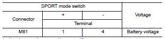
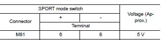
- Check the voltage between sport mode switch harness connector terminals.
Is the inspection result normal? Yes >> go to 3.
No >> go to 4.
3.Check intermittent incidente
Refer to gi-39, "intermittent incident".
Is the inspection result normal? Yes >> replace sport mode switch. Refer to dms-76, "removal and installation".
No >> replace the fuse after repair the applicable circuit.
4.Check sport mode switch illumination power supply (2)
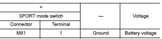
Check the voltage between sport mode switch harness connector and ground.
Is the inspection result normal? Yes >> go to 7.
No >> go to 5.
5.Check fuse
- Turn off the headlamp.
- Turn ignition switch OFF.
- Pull out #37 fuse. Refer to pg-47, "terminal arrangement".
- Check that the fuse is not fusing.
Is the inspection result normal? Yes >> go to 6.
No >> replace the fuse after repair the applicable circuit.
6.Check sport mode switch illumination power supply circuit
- Disconnect IPDM E/R harness connector E45. Refer to INL-26, "Wiring Diagram".
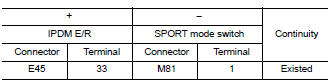
- Check the continuity between ipdm e/r harness connector and sport mode switch harness connector.
- Also check harness for short to ground.
Is the inspection result normal? Yes >> perform ipdm e/r auto active test and check tail lamp relay operation. Refer to pcs-9, "diagnosis description" (with intelligent key), pcs-37, "diagnosis description" (without intelligent key).
No >> repair or replace error-detected parts.
7.Check ground circuit
- Turn off the headlamp.
- Turn ignition switch OFF
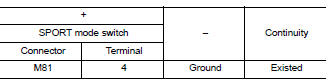
- Check continuity between sport mode switch harness connector terminal and ground.
Is the inspection result normal? Yes >> check intermittent incident. Refer to gi-39, "intermittent incident".
No >> repair or replace error-detected parts.
8.Check sport mode switch circuit
- Turn ignition switch OFF.
- Disconnect sport mode switch harness connector.
- Turn ignition switch ON.
- Check voltage between sport mode switch harness connector terminals.
Is the inspection result normal? Yes >> go to 13.
No >> go to 9.
9.Check ground circuit
- Turn ignition switch off.
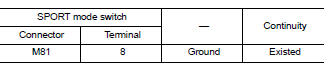
- Check the continuity between SPORT mode switch harness connector and ground.
Is the inspection result normal? Yes >> go to 10.
No >> repair or replace damaged parts.
10.Check circuit between combination meter and sport mode switch (1)
- Disconnect combination meter harness connector m24.
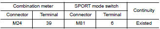
- Check continuity between combination meter harness connector terminal and sport mode switch harness connector terminal
Is the inspection result normal? Yes >> go to 11.
No >> repair or replace damaged parts.
11.Check circuit between combination meter and sport mode switch (2)
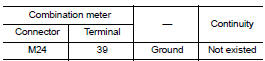
Check continuity between combination meter harness connector terminal and sport mode switch harness connector terminal.
Is the inspection result normal? Yes >> go to 12.
No >> repair or replace damaged parts.
12.Check combination meter input/output signal
- Connect all of disconnected connectors.
- Check input/output signal of combination meter. Refer to mwi-20, "reference value".
Is the inspection result normal? Yes >> check intermittent incident. Refer to gi-39, "intermittent incident".
No >> replace combination meter. Refer to mwi-77, "removal and installation".
13.Check sport mode switch
Check sport mode switch. Refer to dms-37, "component inspection".
Is the inspection result normal?
Yes >> check intermittent incident. Refer to gi-39, "intermittent incident".
No >> replace sport mode switch. Refer to dms-39, "removal and installation".
Component inspection
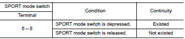
1.Check sport mode switch
Check continuity between sport mode switch connector terminals.
Is the inspection result normal? Yes >> inspection end
No >> replace sport mode switch. Refer to dms-76, "removal and installation".
 Basic inspection
Diagnosis and repair work flow
Work flow
Detailed flow
1.Obtain information about symptom
Interview the customer to obtain as much information as possible about the
conditions and environment un ...
 Symptom diagnosis
The sport mode indicator lamp does not turn on
Description
The sport mode indicator lamp does not turn on when the sport mode switch is
operated.
Diagnosis procedure
1.Perform combination meter ...
Other materials:
Warning/indicator lights
Warning
light
Name
Anti-lock Braking
System (ABS) warning
light
Brake warning light
Charge warning light
Door open warning
light
Engine oil pressure
warning light
Low fuel ...
Automatic operation
Heating (A/C OFF)
The air conditioner does not activate. When you
need to heat only, use this mode.
Press the A/C button. (A/C OFF will be
displayed and A/C indicator will turn off.)
Use the temperature control buttons to set
the desired temperature.
The temperature of the passenge ...
Fuel (Regular Unleaded Gasoline Recommended)
Use unleaded regular gasoline with an octane rating of at least 87 AKI
(Anti-Knock Index) number (Research
octane number 91). E-85 fuel (85% fuel ethanol, 15% unleaded gasoline) may only
be used in vehicles specifically
designed for E-85 fuel (i.e. Flexible Fuel Vehicle - FFV models).
CAUTION ...
