Nissan Sentra Service Manual: Combination meter
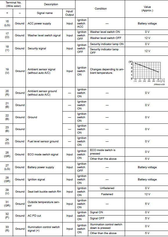
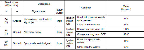
Reference Value
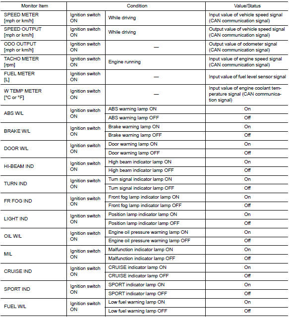
VALUES ON THE DIAGNOSIS TOOL
NOTE:
The following table includes information (items) inapplicable to this vehicle. For information (items) applicable to this vehicle, refer to CONSULT display items.
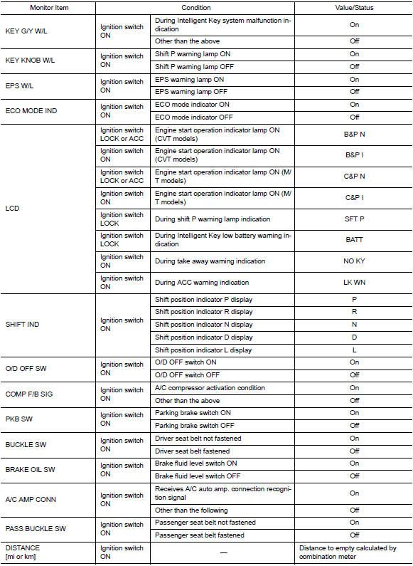

Note:
Some items are not available according to vehicle specification.
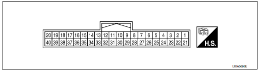
Terminal layout
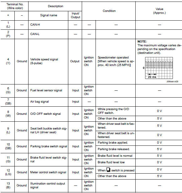
Physical values
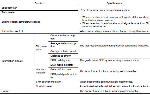
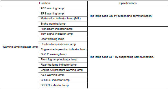
Fail-Safe
The combination meter activates the fail-safe control if can communication with each unit is malfunctioning.
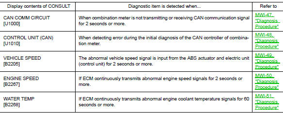
DTC Index

 Bcm (body control module)
List of ECU Reference
...
Other materials:
P014C, P014D, P015A, P015B A/F Sensor 1
DTC Logic
DTC DETECTION LOGIC
To judge the malfunction of A/F sensor 1, this diagnosis measures response
time of the A/F signal computed
by ECM from the A/F sensor 1 signal. The time is compensated by engine operating
(speed and load), fuel
feedback control constant, and the A/F sensor 1 tem ...
Service data and specifications
Wheel Bearing
Drive Shaft
Drive Shaft Specifications
*: Always check with the Parts Department for the latest parts information.
Dynamic Damper Specifications
...
Parking lamp circuit
Description
The ipdm e/r (intelligent power distribution module engine room) controls the
tail lamp relay based on inputs
from the bcm over the can communication lines. When the tail lamp relay is
energized, power flows through
fuse 36, located in the ipdm e/r. Power then flows to the front ...
