Nissan Sentra Service Manual: Clutch pedal
Exploded View
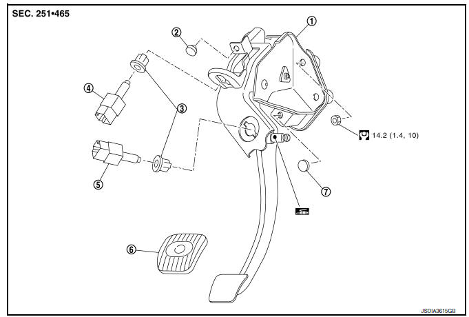
- Clutch pedal
- Stopper rubber
- Clip
- Clutch interlock switch (if equipped)
- Clutch pedal position switch (if equipped)
- Pedal pad
- Pedal stopper rubber
Removal and Installation
REMOVAL
- Remove instrument lower panel LH. Refer to IP-21, "Removal and Installation".
- Disconnect the harness connector from the clutch pedal position switch (if equipped).
- Disconnect the harness connector from the clutch interlock switch (if equipped).
- Disconnect clip of harness from clutch pedal.
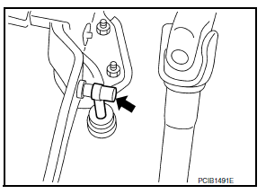
- Remove clutch master cylinder rod end from clutch pedal.
- Remove clutch pedal position switch and clip from clutch pedal (if equipped).
- Remove clutch interlock switch and clip from clutch pedal (if equipped).
- Remove clutch pedal from the vehicle
- Remove pedal pad from clutch pedal.
- Remove stopper rubber and pedal stopper rubber from clutch pedal, using a suitable remover.
INSTALLATION
Installation is in the reverse order of removal.
CAUTION:
After applying recommended grease, press clutch master cylinder rod end into clutch pedal until it stops.
Inspection and Adjustment
INSPECTION AFTER REMOVAL
- Check clutch pedal for bend, damage, or a cracked weld. If bend, damage, or a cracked weld is found, replace clutch pedal.
- Check pedal stopper rubber (if equipped). If damage or deformation is
found, replace pedal stopper rubber.
(if equipped)
- Check stopper rubber. If damage or deformation is found, replace stopper rubber.
- Check pedal pad. If wear or damage is found, replace pedal pad.
INSPECTION AFTER INSTALLATION
- Check the height of clutch pedal. Refer to CL-5, "Inspection and Adjustment".
- Check the clutch interlock switch position (if equipped). Refer to CL-5, "Inspection and Adjustment".
- Check the clutch pedal position switch position (if equipped). Refer to CL-5, "Inspection and Adjustment".
ADJUSTMENT AFTER INSTALLATION
- Adjust the clutch interlock switch position (if equipped). Refer to CL-5, "Inspection and Adjustment".
- Adjust the clutch pedal position switch position (if equipped). Refer to CL-5, "Inspection and Adjustment".

 Clutch master cylinder
Exploded View
Reservoir hose
Reservoir tank
Clutch master cylinder
Removal and Installation
REMOVAL
CAUTION:
Keep painted surface on the body or other parts free of clutch
flui ...
Other materials:
Removal and installation
Power socket
Removal and installation
Front console power socket
Removal
Remove the cvt/mt shift selector finisher. Refer to ip-14, "exploded
view".
Remove cap from the front console power socket.
Remove the screws (a) and the storage bin (1).
Disconnect the harness ...
U1117 Lost communication (ABS)
DTC Logic
DTC DETECTION LOGIC
DTC
CONSULT screen terms
[Trouble diagnosis content]
DTC detection condition
Possible causes
U1117
LOST COMM (ABS)
[Lost Communication With
ABS]
When the ignition switch is ON, TCM is unable
to receive the CAN communications ...
Precaution
Precaution for Supplemental Restraint System (SRS) "AIR BAG" and "SEAT
BELT PRE-TENSIONER"
The Supplemental Restraint System such as “AIR BAG” and “SEAT BELT PRE-TENSIONER”,
used along
with a front seat belt, helps to reduce the risk or severity of injur ...
