Nissan Sentra Service Manual: C1115 ABS Sensor [abnormal signal]
DTC Logic
DTC DETECTION LOGIC
| DTC | Display Item | Malfunction detected condition | Possible causes |
| C1115 | ABS SENSOR [ABNORMAL SIGNAL] | When difference in wheel speed between any wheel and others is detected while the vehicle is driven, because of installation of tires other than specified. |
|
DTC CONFIRMATION PROCEDURE
1.CHECK SELF DIAGNOSTIC RESULT
 With CONSULT
-
Start engine and drive vehicle at approximately 30 km/h (19 MPH) or more for approximately 1 minute.
-
Perform self diagnostic result.
Is DTC C1115 detected? YES >> Proceed to diagnosis procedure. Refer to BRC-68, "Diagnosis Procedure".
NO >> Inspection End.
Diagnosis Procedure
Regarding Wiring Diagram information, refer to BRC-44, "Wiring Diagram".
CAUTION:
Do not check between wheel sensor terminals.
1.CONNECTOR INSPECTION
-
Disconnect ABS actuator and electric unit (control unit) connector E33 and wheel sensor connector of wheel with DTC.
-
Check terminals for deformation, disconnection, looseness or damage.
Is the inspection result normal? YES >> GO TO 2.
NO >> Repair or replace as necessary.
2.CHECK WHEEL SENSOR OUTPUT SIGNAL
-
Connect ABS active wheel sensor tester (J-45741) to wheel sensor using appropriate adapter
-
Turn on the ABS active wheel sensor tester power switch.
NOTE:
The green POWER indicator should illuminate. If the POWER indicator does not illuminate, replace the battery in the ABS active wheel sensor tester before proceeding.
-
Spin the wheel of the vehicle by hand and observe the red SENSOR indicator on the ABS active wheel sensor tester. The red SENSOR indicator should flash on and off to indicate an output signal.
NOTE:
If the red SENSOR indicator illuminates but does not flash, reverse the polarity of the tester leads and retest.
Does the ABS active wheel sensor tester detect a signal? YES >> GO TO 3.
NO >> Replace the wheel sensor. Refer to BRC-106, "FRONT WHEEL SENSOR : Removal and Installation" or BRC-107, "REAR WHEEL SENSOR : Removal and Installation".
3.CHECK TIRES
Check the inflation pressure, wear and size of each tire.
Is the inspection result normal?
YES >> GO TO 4.
NO >> Adjust tire pressure, or replace tire(s).
4.Check wiring harness for short circuit
Check continuity between wheel sensor connector terminals and ground of wheel with DTC.
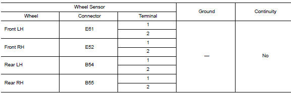
Is the inspection result normal? YES >> GO TO 5.
NO >> Repair the circuit.
5.Check wiring harness for open circuit
Check continuity between ABS actuator and electric unit (control unit) connector E33 and wheel sensor connector of wheel with DTC.
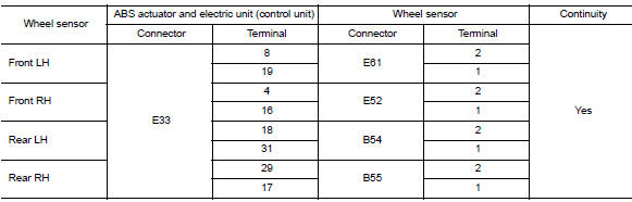
Is the inspection result normal? YES >> Replace the ABS actuator and electric unit (control unit). Refer to BRC-110, "Removal and Installation".
NO >> Repair the circuit.
 C1113, C1145, C1146 Yaw rate/side/decel G Sensor
DTC Logic
DTC DETECTION LOGIC
DTC
Display Item
Malfunction detected condition
Possible causes
C1113
G SENSOR
When a malfunction is detected in longitunal G sensor
s ...
 C1116 Stop lamp switch
DTC Logic
DTC DETECTION LOGIC
DTC
Display item
Malfunction detected condition
Possible cause
C1116
STOP LAMP SW
When stop lamp switch circuit is open.
Harn ...
Other materials:
Precaution for Supplemental Restraint System (SRS)
"AIR BAG" and "SEAT BELT PRE-TENSIONER"
The Supplemental Restraint System such as “AIR BAG” and “SEAT BELT PRE-TENSIONER”,
used along
with a front seat belt, helps to reduce the risk or severity of injury to the
driver and front passenger for certain
types of collision. Information necessary to service the system ...
Clutch disc and clutch cover
Exploded View
Flywheel
Clutch disc
Clutch cover
Input shaft
First step
Final step
Apply lithium-based grease
including molybdenum disulphide.
Removal and Installation
CAUTION:
Do not reuse CSC (Concentric Slave Cylinder). The CSC slides back
to the original posit ...
Diagnosis description : counter system
RELATIONSHIP BETWEEN MIL, 1ST TRIP DTC, DTC, AND DETECTABLE ITEMS
When a malfunction is detected for the first time, the 1st trip DTC and
the 1st trip freeze frame data are
stored in the ECM memory.
When the same malfunction is detected in two consecutive trips, the DTC
and the freeze ...
