Nissan Sentra Service Manual: System description
Component parts
AUTOMATIC DOOR LOCK/UNLOCK FUNCTION
AUTOMATIC DOOR LOCK/UNLOCK FUNCTION : Component Parts Location
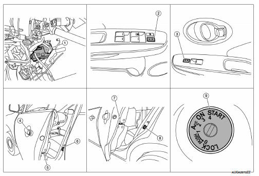
- BCM (view with instrument panel removed)
- Main power window and door lock/unlock switch
- Power window and door lock/unlock switch RH
- Front door lock key cylinder switch LH
- Front door lock actuator LH (RH similar)
- Front door switch LH (RH similar)
- Rear door lock actuator LH (RH similar)
- Rear door switch LH (RH similar)
- Key switch
AUTOMATIC DOOR LOCK/UNLOCK FUNCTION : Component Description
| Item | Function |
| BCM | Controls the door lock function |
| Door lock and unlock switch | Input lock or unlock signal to BCM. |
| Door lock actuator | Output lock/unlock signal from BCM and locks/unlocks each door. |
| Door switch | Input door open/close condition to BCM. |
| Key switch | Input key switch condition to BCM. |
| Front door lock key cylinder switch LH | Input lock or unlock signal to the BCM. |
| ABS actuator and electric unit (control unit) | Transmits vehicle speed signal to CAN communication line. |
| Ignition switch | Input ignition switch ON/OFF condition to BCM. |
Power door lock system
Power door lock system : component parts location
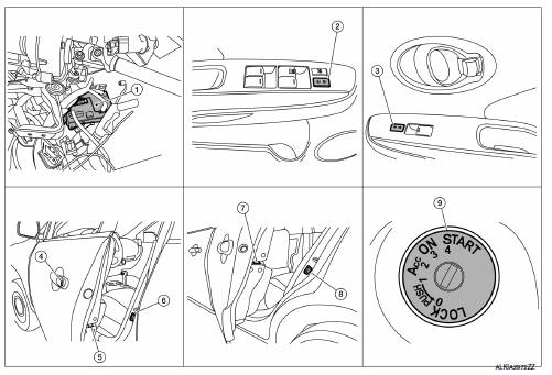
- BCM (view with instrument panel removed)
- Main power window and door lock/unlock switch
- Power window and door lock/unlock switch RH
- Front door lock key cylinder switch LH
- Front door lock actuator LH (RH similar)
- Front door switch LH (RH similar)
- Rear door lock actuator LH (RH similar)
- Rear door switch LH (RH similar)
- Key switch
Power door lock system : component description
| Item | Function |
| BCM | Controls the door lock function. |
| Door lock and unlock switch | Input lock or unlock signal to BCM. |
| Door lock actuator | Output lock/unlock signal from BCM and locks/unlocks each door. |
| Door switch | Input door open/close condition to BCM. |
| Key switch | Input key switch condition to BCM. |
| Front door lock key cylinder switch LH | Input lock or unlock signal to the BCM. |
| ABS actuator and electric unit (control unit) | Transmits vehicle speed signal to CAN communication line. |
| Ignition switch | Input ignition switch ON/OFF condition to BCM. |
Remote keyless entry system
REMOTE KEYLESS ENTRY SYSTEM : Component Parts Location
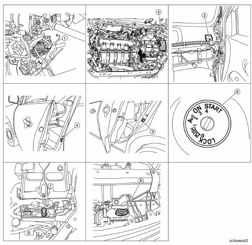
- BCM (view with instrument panel removed)
- IPDM E/R
- Remote keyless entry receiver (view with instrument panel removed)
- Front door switch LH (RH similar)
- Rear door switch LH (RH similar)
- Key switch
- Horn relay
- Horn
REMOTE KEYLESS ENTRY SYSTEM : Component Description
| Item | Function |
| BCM | Controls the door lock function. |
| Door lock and unlock switch | Input lock or unlock signal to BCM. |
| Door switch | Input door open/close condition to BCM. |
| Key switch | Input key switch condition to BCM. |
| Remote keyless entry receiver | Receives lock/unlock signal from the keyfob, and then transmits to BCM. |
| Key switch | Input key switch ON/OFF condition to BCM. |
| Horn | Provides audible warning in panic mode. |
Trunk lid opener system
Trunk lid opener system : component parts location
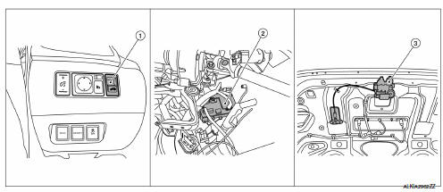
- Trunk lid opener switch
- BCM (view with instrument panel removed
- Trunk lid opener assembly (trunk lid opener actuator and trunk room lamp switch)
Trunk lid opener system : component description
| Item | Function |
| BCM | Controls the trunk lid opener system. |
| Trunk lid opener actuator | Releases the mechanical latch to open the trunk lid. |
| Trunk lid opener switch | Inputs the trunk open request to the BCM. |
| Trunk room lamp switch | Inputs the trunk lid open/close condition to the BCM. |
System (power door lock system)
Automatic door lock/unlock function
Automatic door lock/unlock function : system diagram
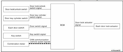
Automatic door lock/unlock function : system description
DOOR LOCK FUNCTION
- The door lock and unlock switch (driver side) is built into power window main switch.
- The door lock and unlock switch (passenger side) is on door trim.
- Interlocked with the locking operation of door lock and unlock switch, door lock actuators of all doors are locked.
- Interlocked with the unlocking operation of door lock and unlock switch, door lock actuators of all doors are unlocked.
Door Key Cylinder
- With the door key inserted in the door key cylinder on driver side, turning it to “LOCK”, will lock door lock actuator of all doors.
- With the door key inserted in the door key cylinder on driver side, turning it to “UNLOCK” once unlocks the driver side door lock actuator; turning it to “UNLOCK” again within 60 seconds after the first unlock operation unlocks all of the other doors. - (SELECTIVE UNLOCK OPERATION)
Selective unlock operation mode can be changed using “DOOR LOCK-UNLOCK SET” mode in “WORK SUPPORT”.
Refer to BCS-87, "DOOR LOCK : CONSULT Function (BCM - DOOR LOCK)".
AUTOMATIC DOOR LOCKS (LOCK OPERATION)
The automatic door locks function is the function that locks all doors linked with the vehicle speed or shift position.
Vehicle Speed Sensing Auto Door Lock*1
All doors are locked when the vehicle speed reaches 24 km/h (15 MPH) or more.
BCM outputs the lock signal to all door lock actuators when it detects that the ignition switch is turned ON, all doors are closed and the vehicle speed received from the combination meter via CAN communication becomes 24 km/h (15 MPH) or more.
If a door is opened and closed at any time during one ignition cycle (OFF → ON), even after initial auto door lock operation has taken place, the BCM will relock all doors when the vehicle speed reaches 24 km/h (15 MPH) or more again.
Setting change of Automatic Door Locks (LOCK) Function
The LOCK operation setting of the automatic door locks function can be changed.
 With CONSULT
The ON/OFF switching of the automatic door locks (LOCK) function and the type selection of the automatic door locks (LOCK) function can be performed at the WORK SUPPORT setting of CONSULT. Refer to BCS-87, "DOOR LOCK : CONSULT Function (BCM - DOOR LOCK)".
 Without CONSULT
The automatic door locks (LOCK) function can be switched ON/OFF by performing the following operation.
- Close all doors (door switch OFF)
- Push the ignition switch to the ON position
- Press and hold the door lock and unlock switch for 5 seconds or more in the lock direction within 20 seconds after turning the ignition switch ON.
- The switching is completed when the hazard lamp blinks.
OFF → ON : 2 blinks
ON → OFF : 1 blink
- The ignition switch must be turned OFF and ON again between each setting change.
AUTOMATIC DOOR LOCKS (UNLOCK OPERATION)
The automatic door locks (UNLOCK) function is the function that unlocks all doors linked with the key position or shift position.
IGN OFF Interlock Door Unlock*1
All doors are unlocked when the power supply position is changed from ON to OFF.
BCM outputs the unlock signal to all door lock actuators when it detects that the power supply position is changed from ignition switch ON to OFF.
Setting change of Automatic Door Locks (UNLOCK) Function
The UNLOCK operation setting of the automatic door locks function can be changed.
 With CONSULT
The ON/OFF switching of the automatic door locks (UNLOCK) function and the type selection of the automatic door locks (UNLOCK) function can be performed at the WORK SUPPORT setting of CONSULT. Refer to BCS- 87, "DOOR LOCK : CONSULT Function (BCM - DOOR LOCK)".
 Without CONSULT
The automatic door locks (UNLOCK) function can be switched ON/OFF by performing the following operation.
- Close all doors (door switch OFF)
- Place the ignition switch in the ON position
- Press and hold the door lock and unlock switch for 5 seconds or more in the unlock direction within 20 seconds after turning the power supply position ON.
- The switching is completed when the hazard lamp blinks.
OFF → ON : 2 blinks
ON → OFF : 1 blink
- The ignition switch must be turned OFF and ON again between each setting change.
*1: This function is set to ON before delivery.
Power door lock system
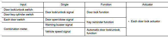
POWER DOOR LOCK SYSTEM : System Diagram
POWER DOOR LOCK SYSTEM : System Description
| Switch | Input/output signal to BCM | BCM function | Actuator |
| Main power window and door lock/unlock switch | Door lock/unlock signal | Door lock/Power window and door lock/ unlock control | Door lock actuator |
| Power window and door lock/unlock switch RH | |||
| Front door lock key cylinder switch LH |
DOOR LOCK FUNCTION
Functions Available by Operating the Door Lock and Unlock Switches on Driver Door and Passenger Door
- Interlocked with the locking operation of door lock and unlock switch, door lock actuators of all door lock actuators are locked.
- Interlocked with the unlocking operation of door lock and unlock switch, door lock actuators of all door lock actuators are unlocked.
Functions Available by Operating the Key Cylinder Switch on Driver Door
- Interlocked with the locking operation of door key cylinder, door lock actuators of all door lock actuators are locked.
Selective Unlock Operation
- When door key cylinder is unlocked, door lock actuator driver side is unlocked.
- When door key cylinder is unlocked for the second time within 5 seconds after the first operation, door lock actuators on all doors are unlocked.
Select unlock operation mode can be changed using DOOR LOCK-UNLOCK SET mode in “WORK SUPPORT”.
Refer to BCS-87, "DOOR LOCK : CONSULT Function (BCM - DOOR LOCK)".
Remote keyless entry system
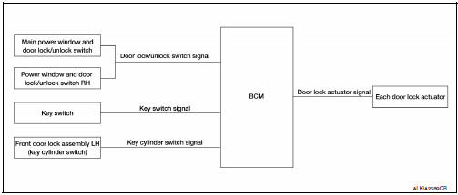
Remote keyless entry system : system diagram
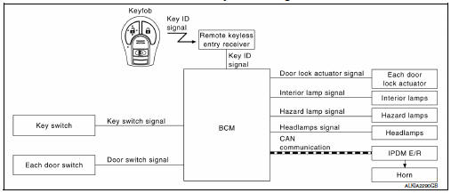
Remote keyless entry system : system description
The remote keyless entry system can be locked and unlocked by pressing door lock and unlock button of keyfob.
DOOR LOCK AND UNLOCK OPERATION
- When door lock and unlock button of keyfob is pressed, door lock and unlock signal transmits from keyfob to BCM via remote keyless entry receiver.
- When BCM receives the door lock and unlock signal, it operates door lock actuator, flashes the hazard lamp (lock: 2 times, unlock: 1 time) and horn chirp signal to IPDM E/R at the same time as a reminder.
- IPDM E/R honks horn (lock: 1 time) as a reminder.
OPERATION CONDITION
| Remote controller operation | Operation condition |
| Lock/unlock | Key switch is OFF. Mechanical key is removed from the ignition cylinder. |
OPERATION AREA
To ensure that the keyfob works effectively, use within 10 m (33ft) range of the vehicle, however the operable range may differ according to surroundings.
SELECTIVE UNLOCK OPERATION
When door lock is unlocked, pressing LOCK button on keyfob once will lock all doors. When door lock is locked, pressing UNLOCK button on keyfob will unlock driver side door. Pressing UNLOCK button on keyfob second time within 5 seconds from the first time will unlock all doors.
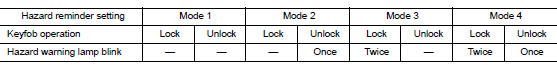
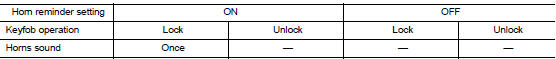
HAZARD AND HORN REMINDER
When the doors are locked or unlocked by keyfob, power is supplied to sound horn and flash hazard warning lamps as a reminder The hazard and horn reminder has C mode (horn chirp mode) and S mode (non-horn chirp mode).
How to Change Hazard and Horn Reminder Modes
 With CONSULT
Hazard and horn reminders can be changed using "WORK SUPPORT" mode in "MULTI REMOTE ENT".
Hazard and horn reminders do not operate if any door switch is ON (any door is OPEN).
Hazard reminder can be changed using “HAZARD LAMP SET” mode in “WORK SUPPORT”.
Horn reminder can be changed using “HORN CHIRP SET” mode in “WORK SUPPORT”.
Refer to BCS-89, "MULTI REMOTE ENT : CONSULT Function (BCM - MULTI REMOTE ENT)".
 Without CONSULT
Refer to Owner’s Manual for instructions.
AUTO DOOR LOCK OPERATION
When all doors are locked, ignition switch is OFF and key switch is OFF (mechanical key is removed from the ignition cylinder), doors are unlocked with keyfob button. When BCM does not receive the following signals within 1 minute, all doors are locked
- Door switch is ON (door is opened)
- Door is locked
- Ignition switch is ON
- Key switch is ON (mechanical key is inserted in the ignition cylinder)
Auto door lock mode can be changed by “AUTO LOCK SET” mode in “WORK SUPPORT”. Refer to BCS-89, "MULTI REMOTE ENT : CONSULT Function (BCM - MULTI REMOTE ENT)".
PANIC ALARM OPERATION
When key switch is OFF (mechanical key is removed from the ignition cylinder), BCM turns ON and OFF horn and headlamp intermittently with input of PANIC ALARM signal from keyfob.
BCM outputs to headlamps and IPDM E/R for panic alarm signal (horn signal) via CAN communication lines.
The alarm automatically turns OFF after 25 seconds or when BCM receives any signal from keyfob.
Panic alarm operation mode can be changed using “PANIC ALARM SET” mode in “WORK SUPPORT”.
Refer to BCS-89, "MULTI REMOTE ENT : CONSULT Function (BCM - MULTI REMOTE ENT)".
INTERIOR LAMP TIMER OPERATION
When the following conditions occur, remote keyless entry system turns on interior lamp for 15 seconds with input of UNLOCK signal from keyfob. For detailed description, refer to DLK-216, "POWER DOOR LOCK SYSTEM : System Description".
- Interior room lamp switch is in the DOOR position
- Door switch OFF (when all the doors are closed).
System (trunk lid opener system)
System Description
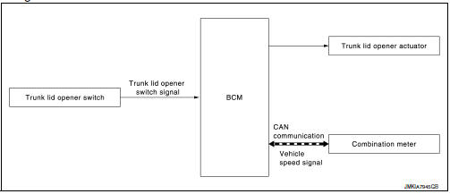
TRUNK LID OPENER OPERATION
When trunk lid opener switch is ON, BCM operates trunk lid opener actuator.
OPERATION CONDITION
If the following conditions are satisfied, trunk open operation is performed.
| Trunk lid opener switch operation | Operation condition |
| Trunk lid open |
|
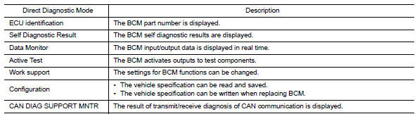
Diagnosis system (BCM)
Common item
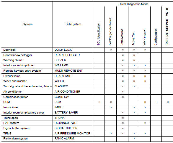
Common item : consult function (bcm - common item)
APPLICATION ITEM
CONSULT performs the following functions via CAN communication with BCM.
SYSTEM APPLICATION
BCM can perform the following functions.
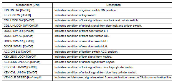
Door lock
Door lock : consult function (bcm - door lock)
DATA MONITOR
ACTIVE TEST

WORK SUPPORT
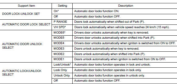
* : Initial setting
Trunk
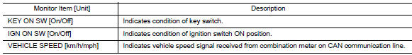
Trunk : consult function (bcm - trunk)
DATA MONITOR
 Preparation
Special service tools
The actual shape of the tools may differ from those illustrated here.
Commercial service tools
Clip list
Descriptions for Clips
Replace any clips which are dama ...
 Ecu diagnosis information
BCM
List of ecu reference
...
Other materials:
Precaution for Supplemental Restraint System
(SRS) "AIR BAG" and "SEAT BELT PRE-TENSIONER"
The Supplemental Restraint System such as “AIR BAG” and “SEAT BELT PRE-TENSIONER”,
used along
with a front seat belt, helps to reduce the risk or severity of injury to the
driver and front passenger for certain
types of collision. Information necessary to service the system ...
Checking bulbs
With all doors closed, apply the parking brake
and place the ignition switch in the ON position
without starting the engine. The following lights
will come on:
If equipped, the following lights come on briefly
and then go off:
If any light fails to come on, it may indicate
an open circuit ...
Service Notice and Precautions for Road Wheel
Genuine NISSAN aluminum wheel is designed for each type of vehicle. Use
it on the specified vehicle only.
Use Genuine NISSAN parts for the road wheels, valve caps and wheel nuts.
Always use them after adjusting the wheel balance. For the balance
weights, use Genuine NISSAN aluminum
wh ...
