Nissan Sentra Service Manual: Symptom diagnosis
NOISE, VIBRATION AND HARSHNESS (NVH) TROUBLESHOOTING
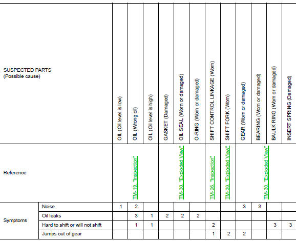
NVH Troubleshooting Chart
Use the chart below to find the cause of the symptom. The numbers indicate the order of the inspection. If necessary, repair or replace these parts.
 DTC/Circuit diagnosis
POSITION SWITCH
BACK-UP LAMP SWITCH
BACK-UP LAMP SWITCH : Component Inspection
1.CHECK BACK-UP LAMP SWITCH
Disconnect position switch harness connector. Refer to TM-21, "Removal
and In ...
 Periodic maintenance
M/T OIL
Inspection
OIL LEAKAGE
Make sure that gear oil is not leaking from transaxle or around it.
OIL LEVEL
Remove filler plug (1) and gasket from transaxle case.
Check the oil level from f ...
Other materials:
Front wiper drive assembly
Exploded view
Wiper blade (RH)
Wiper arm (RH)
Wiper drive assembly
Wiper arm (LH)
Wiper blade (LH)
Removal and installation
REMOVAL
Remove the cowl top. Refer to EXT-26, "Removal and Installation".
Disconnect the harness connector from the wiper drive assembly.
...
Water outlet
Exploded View
CVT MODELS
Water control valve
Rubber ring
Radiator hose (upper)
Clamp
Water outlet
CVT oil warmer hose (outlet)
Heater hose (inlet)
Heater hose (outlet)
Electric throttle control actuator hose
(outlet)
Electric throttle control actuator hose
(inlet)
E ...
Symptom diagnosis
Squeak and rattle trouble diagnoses
Work flow
Customer interview
Interview the customer if possible, to determine the conditions that exist
when the noise occurs. Use the diagnostic
worksheet during the interview to document the facts and conditions when the
noise occurs and any
custom ...
