Nissan Sentra Service Manual: Removal and installation
Generator
Exploded view
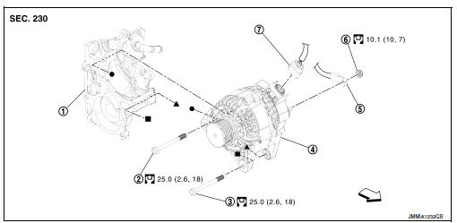
- Thermostat housing
- Generator bolt (upper)
- Generator bolt (lower)
- Generator
- B” terminal harness
- “B” terminal nut
- Generator harness connector
 Front
Front
Removal and installation
Note:
When removing components such as hoses,tubes\lines,etc,cap or plug openings to prevent fluid from spilling.
Removal
- Disconnect the battery negative terminal. Refer to PG-50, "Removal and Installation (Battery)".
- Remove cooling fan. Refer to CO-17, "Removal and Installation".
- Remove drive belt. Refer to em-15, "removal and installation".
- Disconnect generator harness connector.
- Remove “B” terminal nut, and then disconnect “B” terminal harness.
- Remove generator bolt (upper).
- Completely loosen generator bolt (lower) (1), and pull it out until the bolt head is in contact with the side member. And then, remove the generator (2) by pulling it forward.
 : Front
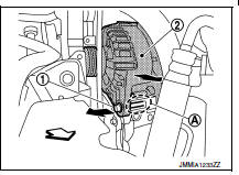
Note:
The generator can be removed together with the bolts by pulling it forward and using the thermostat housing bolt hole cutout (a).
- Remove generator upward from the vehicle.
Installation
- Installation is in the reverse order of removal.
- Refill engine coolant. Refer to co-12, "changing engine coolant".
Caution:
- Temporarily tighten the generator bolts in order from the lower to the upper, and then tighten them in order from the upper to the lower.
- For the generator, the front side (pulley side) surface is the reference surface. Fit the reference surface to the generator mounting part, and then tighten the bolts.
- Be careful to tighten “b” terminal nut carefully.
- For this model, the power generation voltage variable control system that controls the power generation voltage of the generator has been adopted. Therefore, the power generation voltage variable control system operation inspection should be performed after replacing the generator, and then make sure that the system operates normally. Refer to chg-8, "system description".
Inspection
Generator pulley inspection
Perform the following.
- Make sure that generator pulley does not rattle.
- Make sure that generator pulley nut is tight.
Note:
Replace generator as an assembly if necessary.
 Symptom diagnosis
Charging system
Symptom table
...
 Service data and specifications (SDS)
Generator
*: Always check with the parts department for the latest parts information. ...
Other materials:
Key to Symbols Signifying Measurements or Procedures
...
M&a branch line circuit
Diagnosis procedure
1.Check connector
Turn the ignition switch off.
Disconnect the battery cable from the negative terminal.
Check the terminals and connectors of the combination meter for damage,
bend and loose connection
(unit side and connector side).
Is the inspection result nor ...
Map lamp
Removal and installation
Removal
Lower front edge of map lamp (1) down from the headlining by
releasing the metal clips, then slide forward to clear pawls at
rear.
: Metal clip
Pawl
Disconnect the harness connectors from the map lamp and remove.
Installation
Installation is in t ...
