Nissan Sentra Service Manual: Power supply and ground circuit
Combination meter
COMBINATION METER : Diagnosis Procedure
Regarding Wiring Diagram information, refer to MWI-28, "Wiring Diagram".
1.Check fuses
Check that the following fuses are not blown.
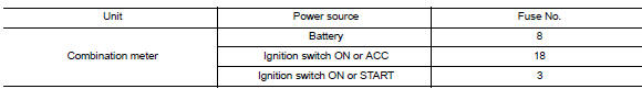
Is the fuse blown? Yes >> replace the blown fuse after repairing the affected circuit.
No >> go to 2.
2.Power supply circuit check
Check voltage between combination meter harness connector m24 terminals 15, 27, 28 and ground
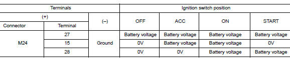
Is the inspection result normal? YES >> GO TO 3.
NO >> Repair or replace harness or connector.
3.Check ground circuit
Check continuity between combination meter harness connector m24 terminals 21, 22, 23 and ground.
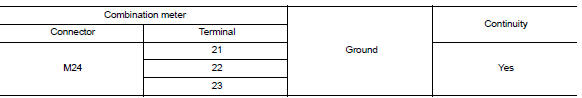
Is the inspection result normal? Yes >> inspection end.
No >> repair or replace harness or connector.
Bcm (body control system) (with intelligent key system)
Bcm (body control system) (with intelligent key system) : diagnosis procedure
Regarding wiring diagram information, refer to bcs-51, "wiring diagram".
1.Check fuses and fusible link
Check that the following fuses and fusible link are not blown.
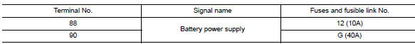
Is the fuse blown? Yes >> replace the blown fuse or fusible link after repairing the affected circuit.
No >> go to 2.
2.Check power supply circuit
- Disconnect bcm connector m85.
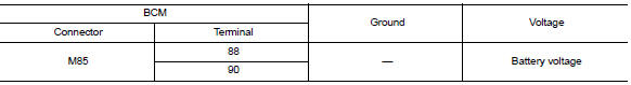
- Check voltage between BCM connector M85 and ground.
Is the inspection result normal? Yes >> go to 3.
No >> repair harness or connector.
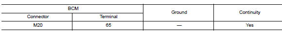
3.Check ground circuit
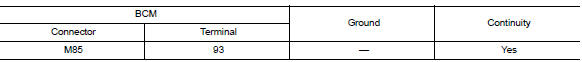
Check continuity between bcm connector m85 and ground.
Is the inspection result normal? Yes >> inspection end.
No >> repair harness or connector.
Bcm (body control system) (without intelligent key system)
Bcm (body control system) (without intelligent key system) : diagnosis procedure
Regarding Wiring Diagram information, refer to BCS-111, "Wiring Diagram".
1.Check fuses and fusible link
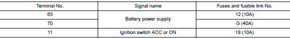
Check that the following fuses and fusible link are not blown.
Is the fuse blown? Yes >> replace the blown fuse or fusible link after repairing the affected circuit.
No >> go to 2.
2.Check power supply circuit
- Turn ignition switch off.
- Disconnect bcm connectors.
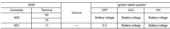
- Check voltage between bcm connector and ground.
Is the inspection result normal? YES >> GO TO 3.
NO >> Repair harness or connector.
3.Check ground circuit
Check continuity between BCM connector and ground.
Is the inspection result normal? Yes >> inspection end.
No >> repair harness or connector.
 B2268 water temp
Description
The engine coolant temperature signal is transmitted from ecm to the
combination meter via can communication.
Dtc logic
Dtc detection logic
Dtc
Consult
Detection condit ...
 Steering switch (meter control switch) signal circuit
Diagnosis Procedure
Regarding wiring diagram information, refer to mwi-28, "wiring diagram".
1.Check combination meter input signal
Turn ignition switch on.
Measure voltage between ...
Other materials:
P0014 EVT control
DTC Logic
DTC DETECTION LOGIC
NOTE:
If DTC P0014 is displayed with DTC P0078, first perform trouble
diagnosis for DTC P0078. Refer to
EC-183, "DTC Logic".
If DTC P0014 is displayed with P1078, first perform trouble diagnosis
for P1078. Refer to EC-359,
"DTC Logic&quo ...
B0097 Rear side air bag satellite sensor RH
Description
DTC B0097 REAR SATELLITE SENSOR RH
The rear side air bag satellite sensor RH is wired to the air bag diagnosis
sensor unit. The air bag diagnosis
sensor unit will monitor the rear side air bag satellite sensor RH for internal
failures and its circuits for communication
errors.
P ...
Parking, license plate and tail
lamps are not turned on
Description
The parking, license plate and tail lamps do not turn on in with any lighting
switch setting.
Diagnosis procedure
1.Combination switch (lighting and turn signal switch) inspection
Check the combination switch (lighting and turn signal switch). Refer to
BCS-72, "Symptom Table ...
