Nissan Sentra Service Manual: Periodic maintenance
Road wheel
Inspection
ALUMINUM WHEEL
- Check tires for wear and improper inflation.
- Check wheels for deformation, cracks and other damage. If deformed, remove wheel and check wheel runout.
- Remove tire from aluminum wheel and mount wheel on a balancer machine.
- Set dial indicator as shown.
- Check runout, if runout value exceeds the limit, replace aluminum wheel.
Limit
Lateral Deflection (A) Refer to WT-54, "Road Wheel".
Radial Deflection (B) Refer to WT-54, "Road Wheel".
STEEL WHEEL
- Check tires for wear and improper inflation.
- Check wheels for deformation, cracks and other damage. If deformed, remove wheel and check wheel runout.
- Remove tire from steel wheel and mount wheel on a balancer machine.
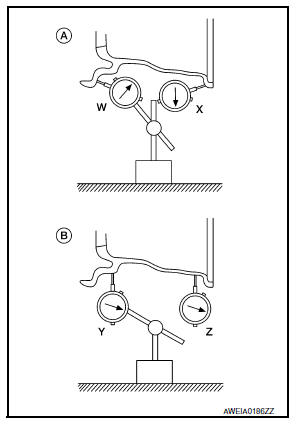
- Set two dial indicators as shown.
- Set each dial indicator to "0".
- Rotate wheel and check dial indicators at several points around the circumference of the wheel.
- Calculate runout at each point as shown below.
Lateral deflection (A) = (W+X)/2
Radial deflection (B) = (Y+Z)/2
- Select maximum positive runout value and the maximum negative
value.
Add the two values to determine total runout.
In case a positive or negative value is not available, use the maximum value (negative or positive) for total runout.
If the total runout value exceeds the limit, replace steel wheel.
Limit
Lateral Deflection (A) Refer to WT-54, "Road Wheel".
Radial Deflection (B) Refer to WT-54, "Road Wheel".
 Noise, vibration and harshness (NVH) troubleshooting
NVH Troubleshooting Chart
Use chart below to find the cause of the symptom. If necessary, repair or
replace these parts.
×: Applicable ...

Other materials:
System description
Component parts
Component parts location
Front tweeter lh (if equipped)
Steering switches
Audio unit
Front tweeter rh (if equipped)
Microphone (if equipped)
Front door speaker lh
Front door speaker RH
Rear speaker rh
Rear speaker lh
Antenna amp.
Window antenna
Bluetoot ...
Audio system voice commands
To access the audio system voice commands:
Press the button.
Say “Audio”
Speak a command from the following available
commands:
Play (AM, FM, etc.)
Allows user to select radio band
Tune AM (number)
Allows user to tune directly to a desired AM
frequency
Tune FM (number)
...
Dtc/circuit diagnosis
Eco mode switch
Component function check
1. Check eco mode switch operation
Turn ignition switch on.
Check ECO mode indicator lamp turns ON/OFF on combination meter when
turn ECO mode switch ON/
OFF.
Is the inspection result normal?
YES >> GO TO 2.
NO >> Proceed to DM ...
