Nissan Sentra Service Manual: P1556, P1557 Battery temperature sensor
DTC Logic
DTC DETECTION LOGIC
NOTE:
If DTC P1556 or P1557 is displayed with DTC P0643, first perform the trouble diagnosis for DTC P0643.
Refer to EC-353, "DTC Logic".
| DTC No. | CONSULT screen terms (Trouble diagnosis content) | DTC detecting condition | Possible cause |
| P1556 | BAT TMP SEN/CIRC (BAT TMP SEN/CIRC) | Signal voltage from Battery temperature sensor remains 0.16V or less for 5 seconds or more. |
|
| P1557 | BAT TMP SEN/CIRC (BAT TMP SEN/CIRC) | Signal voltage from Battery temperature sensor remains 4.84V or more for 5 seconds or more. |
DTC CONFIRMATION PROCEDURE
1.PRECONDITIONING
- Turn ignition switch OFF and wait at least 10 seconds.
- Turn ignition switch ON.
- Turn ignition switch OFF and wait at least 10 seconds
TESTING CONDITION:
Before performing the following procedure, confirm that battery voltage is 10 V or more at idle.
>> GO TO 2.
2.PERFORM DTC CONFIRMATION PROCEDURE
- Start the engine and let it idle at least 10 seconds.
- Check 1st trip DTC.
Is 1st trip DTC detected? YES >> Proceed to EC-386, "Diagnosis Procedure".
NO >> INSPECTION END
Diagnosis Procedure
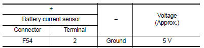
1.CHECK BATTERY TEMPERATURE SENSOR POWER SUPPLY
- Turn ignition switch OFF
- Disconnect battery current sensor harness connector.
- Turn ignition switch ON.
- Check the voltage between battery current sensor harness connector and ground.
Is the inspection result normal? YES >> GO TO 3.
NO >> GO TO 2.
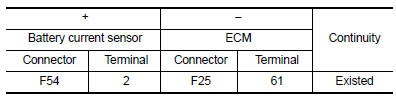
2.CHECK BATTERY TEMPERATURE SENSOR POWER SUPPLY CIRCUIT
- Turn ignition switch OFF.
- Disconnect ECM harness connector.
- Check the continuity between battery current sensor harness connector and ECM harness connector.
- Also check harness for short to ground.
Is the inspection result normal? YES >> Perform the trouble diagnosis for power supply circuit.
NO >> Repair or replace error-detected parts.
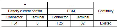
3.CHECK BATTERY TEMPERATURE SENSOR GROUND CIRCUIT
- Turn ignition switch OFF.
- Disconnect ECM harness connector.
- Check the continuity between battery current sensor harness connector and ECM harness connector.
- Also check harness for short to power.
Is the inspection result normal? YES >> GO TO 4.
NO >> Repair or replace error-detected parts.
4.CHECK BATTERY TEMPERATURE SENSOR
Check the battery temperature sensor. Refer to EC-387, "Component Inspection".
Is the inspection result normal? YES >> Check intermittent incident. Refer to GI-39, "Intermittent Incident".
NO >> Replace battery negative cable assembly.
Component Inspection
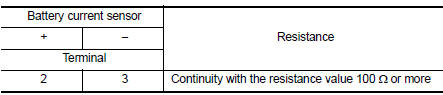
1.CHECK BATTERY TEMPERATURE SENSOR
- Turn ignition switch OFF.
- Disconnect battery current sensor.
- Check the resistance between battery current sensor connector terminals.
Is the inspection result normal? YES >> INSPECTION END
NO >> Replace battery negative cable assembly.
 P1554 Battery current sensor
DTC Logic
DTC DETECTION LOGIC
DTC No.
CONSULT screen terms
(Trouble diagnosis content)
DTC detecting condition
Possible cause
P1554
BAT CURRENT SENSOR
(Battery curr ...
 P1564 ASCD Steering switch
DTC Logic
DTC DETECTION LOGIC
NOTE:
If DTC P1564 is displayed with DTC P0605, first perform the trouble
diagnosis for DTC P0605. Refer to
EC-348, "DTC Logic".
DTC No.
CONSUL ...
Other materials:
Precaution
Precaution for Supplemental Restraint System (SRS) "AIR BAG" and "SEAT
BELT PRE-TENSIONER"
The Supplemental Restraint System such as “AIR BAG” and “SEAT BELT PRE-TENSIONER”,
used along
with a front seat belt, helps to reduce the risk or severity of injur ...
Front wiper motor ground circuit
Diagnosis procedure
Regarding Wiring Diagram information, refer to WW-24, "Wiring Diagram - With
Intelligent Key" or WW-29,
"Wiring Diagram - Without Intelligent Key".
1.Check front wiper motor (gnd) open circuit
Turn the ignition switch OFF.
Disconnect front wiper mot ...
P1574 ASCD Vehicle speed sensor
Description
The ECM receives two vehicle speed sensor signals via CAN communication line.
One is sent from combination
meter, and the other is from TCM (Transmission control module). The ECM uses
these signals for ASCD
control. Refer to EC-51, "AUTOMATIC SPEED CONTROL DEVICE (ASCD) : Sys ...
