Nissan Sentra Service Manual: P0448 EVAP Canister vent control valve
DTC Logic
DTC DETECTION LOGIC
| DTC No. | CONSULT screen terms (Trouble diagnosis content) | DTC detecting condition | Possible cause |
| P0448 | VENT CONTROL VALVE (Evaporative emission system vent control circuit shorted) | EVAP canister vent control valve remains closed under specified driving conditions. |
|
DTC CONFIRMATION PROCEDURE
1.PRECONDITIONING
If DTC Confirmation Procedure has been previously conducted, always perform the following procedure before conducting the next test.
- Turn ignition switch OFF and wait at least 10 seconds.
- Turn ignition switch ON.
- Turn ignition switch OFF and wait at least 10 seconds.
>> GO TO 2.
2.PERFORM DTC CONFIRMATION PROCEDURE
 With CONSULT
- Turn ignition switch ON and wait at least 5 seconds.
- Turn ignition switch OFF and wait at least 10 seconds.
- Turn ignition switch ON and select “DATA MONITOR” mode of “ENGINE” using CONSULT.
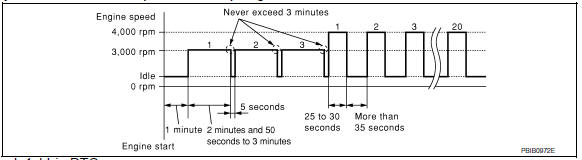
- Start engine and let it idle for at least 1 minute.
- Repeat next procedures three times.
- Increase the engine speed up to 3,000 to 3,500 rpm and keep it for 2 minutes and 50 seconds to 3 minutes.
Never exceed 3 minutes.
- Fully released accelerator pedal and keep engine idle for about 5 seconds.
- Repeat next procedure 20 times.
- Quickly increase the engine speed up to 4,000 to 4,500 rpm or more and keep it for 25 to 30 seconds.
- Fully released accelerator pedal and keep engine idle for at least 35 seconds.
- Check 1st trip DTC.
 With GST
Follow the procedure “With CONSULT” above.
Is 1st trip DTC detected? YES >> Proceed to EC-306, "Diagnosis Procedure".
NO >> INSPECTION END
Diagnosis Procedure
1.CHECK RUBBER TUBE
- Turn ignition switch OFF.
- Disconnect rubber tube connected to EVAP canister vent control valve.
- Check the rubber tube for clogging.
Is the inspection result normal? YES >> GO TO 2.
NO >> Clean rubber tube using an air blower.
2.CHECK EVAP CANISTER VENT CONTROL VALVE
Check the EVAP canister vent control valve. Refer to EC-307, "Component Inspection".
Is the inspection result normal? YES >> GO TO 3.
NO >> Replace EVAP canister vent control valve. Refer to FL-15, "Removal and Installation".
3.CHECK IF EVAP CANISTER IS SATURATED WITH WATER
- Remove EVAP canister with EVAP canister vent control valve and EVAP control system pressure sensor attached.
- Check if water will drain from the EVAP canister.
Does water drain from EVAP canister? YES >> GO TO 4.
NO >> GO TO 6.
4.CHECK EVAP CANISTER
Weigh the EVAP canister with the EVAP canister vent control valve and EVAP control system pressure sensor attached.
The weight should be less than 2.1 kg (4.6 lb).
Is the inspection result normal? YES >> GO TO 6.
NO >> GO TO 5.
5.DETECT MALFUNCTIONING PART
Check the following.
- EVAP canister for damage
- EVAP hose between EVAP canister and vehicle frame for clogging or poor connection
>> Repair hose or replace EVAP canister. Refer to FL-15, "Removal and Installation".
6.CHECK EVAP CONTROL SYSTEM PRESSURE SENSOR CONNECTOR
- Disconnect EVAP control system pressure sensor harness connector.
- Check connectors for water.
Water should not exist.
Is the inspection result normal? YES >> GO TO 7.
NO >> Replace EVAP control system pressure sensor. Refer to FL-15, "Removal and Installation".
7.CHECK EVAP CONTROL SYSTEM PRESSURE SENSOR
Check the EVAP control system pressure sensor. Refer to EC-311, "Component Inspection".
Is the inspection result normal? YES >> Check intermittent incident. Refer to GI-39, "Intermittent Incident".
NO >> Replace EVAP control system pressure sensor. Refer to FL-15, "Removal and Installation".
Component Inspection
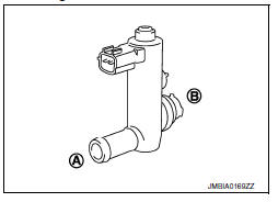
1.CHECK EVAP CANISTER VENT CONTROL VALVE-1
- Turn ignition switch OFF.
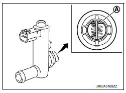
- Remove EVAP canister vent control valve from EVAP canister.
- Check portion
 of EVAP
canister vent control valve for being rusted.
Is it rusted?
YES >> Replace EVAP canister vent control valve. Refer to FL- 15, "Removal and Installation".
NO >> GO TO 2.
2.CHECK EVAP CANISTER VENT CONTROL VALVE-2
 With CONSULT
- Reconnect harness connectors disconnected.
- Turn ignition switch ON.
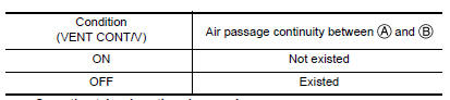
- Perform “VENT CONTROL/V” in “ACTIVE TEST” mode of “ENGINE” using CONSULT.
- Check air passage continuity and operation delay time.
Make sure new O-ring is installed properly.
Operation takes less than 1 second.
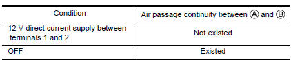
 Without CONSULT
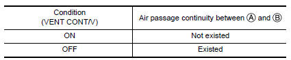
Check air passage continuity and operation delay time under the following conditions
Make sure new O-ring is installed properly.
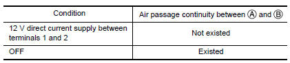
Operation takes less than 1 second.
Is the inspection result normal? YES >> GO TO 3.
NO >> Replace EVAP canister vent control valve. Refer to FL-15, "Removal and Installation".
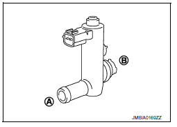
3.CHECK EVAP CANISTER VENT CONTROL VALVE-3
 With CONSULT
- Clean the air passage [portion
![] of EVAP canister vent](images/books/349/13/index144.gif) to
to
 ] of EVAP canister vent
control valve using an air blower. - Perform “VENT CONTROL/V” in “ACTIVE TEST” mode of “ENGINE” using CONSULT.
- Check air passage continuity and operation delay time.
Make sure new O-ring is installed properly.
Operation takes less than 1 second.
 Without CONSULT
- Clean the air passage [portion
![] of EVAP canister vent](images/books/349/13/index149.gif) to
to
 ] of EVAP canister vent
control valve using an air blower. - Check air passage continuity and operation delay time under the following conditions.
Make sure new O-ring is installed properly.
Operation takes less than 1 second.
Is the inspection result normal? YES >> INSPECTION END
NO >> Replace EVAP canister vent control valve. Refer to FL-15, "Removal and Installation".
 P0447 EVAP Canister vent control valve
DTC Logic
DTC DETECTION LOGIC
DTC No.
CONSULT screen terms
(Trouble diagnosis content)
DTC detecting condition
Possible cause
P0447
VENT CONTROL VALVE
(Evaporative ...
 P0451 EVAP Control system pressure sensor
DTC Logic
DTC DETECTION LOGIC
DTC No.
CONSULT screen terms
(Trouble diagnosis content)
DTC detecting condition
Possible cause
P0451
EVAP SYS PRES SEN
(Evaporative e ...
Other materials:
EPS Warning lamp
Component Function Check
1.CHECK THE ILLUMINATION OF THE EPS WARNING LAMP
Check that the EPS warning lamp turns ON when ignition switch
turns ON. Then, EPS warning lamp turns
OFF after the engine is started.
Is the inspection result normal?
YES >> Inspection End.
NO >> Perfo ...
Symptom diagnosis
The sport mode indicator lamp does not turn on
Description
The sport mode indicator lamp does not turn on when the sport mode switch is
operated.
Diagnosis procedure
1.Perform combination meter on board diagnosis
Perform combination meter on board diagnosis. Refer to mwi-16, "descriptio ...
Handling precautions for plastics
Precautions for plastics
When repairing and painting a portion of the body adjacent to plastic
parts, consider their characteristics
(influence of heat and solvent) and remove them if necessary or take
suitable measures to protect them.
Plastic parts should be repaired and painted ...
