Nissan Sentra Service Manual: P0125 ECT Sensor
DTC Logic
DTC DETECTION LOGIC
NOTE:
- If DTC P0125 is displayed with P0116, first perform the trouble diagnosis for DTC P0116. Refer to EC- 196, "DTC Logic".
- If DTC P0125 is displayed with P0117 or P0118, first perform the trouble diagnosis for DTC P0117 or P0118. Refer to EC-198, "DTC Logic".
| DTC No. | CONSULT screen terms (Trouble diagnosis content) | DTC detecting condition | Possible cause |
| P0125 | ECT SENSOR (Insufficient coolant temperature for closed loop fuel control) |
|
|
DTC CONFIRMATION PROCEDURE
1.PRECONDITIONING
If DTC Confirmation Procedure has been previously conducted, always perform the following procedure before conducting the next test.
- Turn ignition switch OFF and wait at least 10 seconds.
- Turn ignition switch ON.
- Turn ignition switch OFF and wait at least 10 seconds.
>> GO TO 2.
2.CHECK ENGINE COOLANT TEMPERATURE SENSOR FUNCTION
 With CONSULT
- Turn ignition switch ON
- Select “DATA MONITOR” mode of “ENGINE” using CONSULT.
- Check that “COOLANT TEMP/S” is above 10°C (50°F).
 With GST
Follow the procedure “With CONSULT” above.
Is it above 5В°C (41В°F)? YES >> INSPECTION END
NO >> GO TO 3.
3.PERFORM DTC CONFIRMATION PROCEDURE
 With CONSULT
- Start engine and run it for 65 minutes at idle speed.
- Check 1st tip DTC.
If “COOLANT TEMP/S” indication increases to more than 10°C (50°F) within 65 minutes, stop engine because the test result will be OK.
CAUTION:
Be careful not to overheat engine.
 With GST
Follow the procedure “With CONSULT” above.
Is 1st trip DTC detected? YES >> Proceed to EC-203, "Diagnosis Procedure".
NO >> INSPECTION END
Diagnosis Procedure
1.CHECK ENGINE COOLANT TEMPERATURE SENSOR
Check the engine coolant temperature sensor. Refer to EC-197, "Component Inspection".
Is the inspection result normal? YES >> GO TO 2.
NO >> Replace engine coolant temperature sensor. Refer to CO-24, "Exploded View".
2.CHECK THERMOSTAT OPERATION
When the engine is cold [lower than 70В°C (158В°F)] condition, grasp lower radiator hose and confirm the engine coolant does not flow.
Is the inspection result normal? YES >> Check intermittent incident. Refer to GI-39, "Intermittent Incident".
NO >> Repair or replace thermostat. Refer to CO-21, "Removal and Installation of Thermostat".
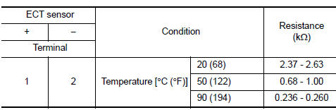
Component Inspection
1.CHECK ENGINE COOLANT TEMPERATURE (ECT) SENSOR
- Turn ignition switch OFF.
- Disconnect ECT sensor harness connector.
- Remove ECT sensor.
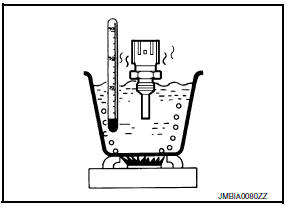
- Check resistance between ECT sensor terminals by heating with hot water as shown in the figure.
Is the inspection result normal? YES >> INSPECTION END
NO >> Replace engine coolant temperature sensor. Refer to CO-24, "Exploded View".
 P0122, P0123 TP Sensor
DTC Logic
DTC DETECTION LOGIC
NOTE:
If DTC P0122 or P0123 is displayed with DTC P0643, first perform the
trouble diagnosis for DTC P0643.
Refer to EC-353, "DTC Logic".
DTC No ...
 P0127 IATSensor
DTC Logic
DTC DETECTION LOGIC
DTC No.
CONSULT screen terms
(Trouble diagnosis content)
DTC detecting condition
Possible cause
P0127
IAT SENSOR-B1
(Intake air temper ...
Other materials:
Doors
When the doors are locked using one of the
following methods, the doors cannot be opened
using the inside or outside door handles. The
doors must be unlocked to open the doors.
WARNING
Always have the doors locked while
driving. Along with the use of seat belts,
this provides ...
P285A Clutch B Pressure
DTC Logic
DTC DETECTION LOGIC
DTC
CONSULT screen terms
(Trouble diagnosis content)
DTC detection condition
Possible causes
P285A
CLUTCH B PRESSURE
(Clutch B Pressure Disengagement
Performance)
The detection conditions continuously for 200
msec or more und ...
Fuel level sensor signal circuit
Description
The fuel level sensor unit and fuel pump detects the approximate fuel level
in the fuel tank and transmits the
fuel level signal to the combination meter.
Component function check
1.Combination meter input signal
Select meter/m&a on consult.
Using FUEL METER of DATA MONI ...
