Nissan Sentra Service Manual: Ipdm e/r (intelligent power distribution module engine room)
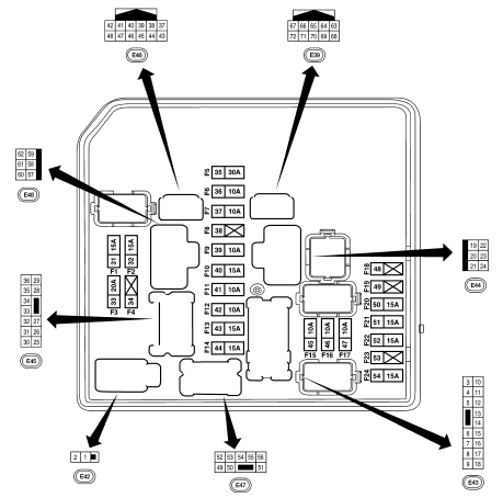
Ipdm e/r terminal arrangement

Note:
Numbers preceded by an "f" represent the fuse numbers imprinted on the ipdm e/r. The other numbers represent the fuse numbers as they appear in the wiring diagrams.
 Fuse, fusible link and relay box
Terminal arrangement
Fuse and fusible link box
...
Other materials:
Unit disassembly and assembly
Moonroof unit assembly
Exploded view
Drain assembly
Glass lid
Weatherstrip
Moonroof rail assembly
Drain hose front (RH)
Moonroof motor assembly
Drain hose front (LH)
Side bracket (LH)
Drain hose rear (LH)
Sunshade stopper (LH)
Sunshade
Sunshade stopper (RH)
Drain hos ...
P0451 EVAP Control system pressure sensor
DTC Logic
DTC DETECTION LOGIC
DTC No.
CONSULT screen terms
(Trouble diagnosis content)
DTC detecting condition
Possible cause
P0451
EVAP SYS PRES SEN
(Evaporative emission system
pressure sensor/switch range/
performance)
ECM detects a sloshing signal fro ...
Tire Pressure Monitoring System (TPMS)
This vehicle is equipped with the Tire Pressure
Monitoring System (TPMS). It monitors tire pressure
of all tires except the spare. When the low
tire pressure warning light is lit, and the CHECK
TIRE PRES warning message is displayed in the
odometer, one or more of your tires is significantly
u ...

