Nissan Sentra Service Manual: Front wiper auto stop signal circuit
Component function check
1. Check front wiper (auto stop) operation
 Consult data monitor
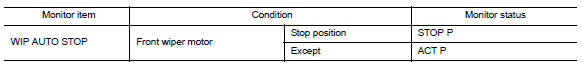
- Select “WIP AUTO STOP” of IPDM E/R DATA MONITOR item.
- Operate the front wiper.
- With the front wiper operation, check the monitor status.
Is the inspection result normal? YES >> Auto stop signal circuit is normal.
NO >> Refer to WW-41, "Diagnosis Procedure".
Diagnosis procedure
Regarding wiring diagram information, refer to ww-24, "wiring diagram - with intelligent key" or ww-29, "wiring diagram - without intelligent key".
1. Check ipdm e/r output voltage
- Turn the ignition switch off
- Disconnect front wiper motor.
- Turn the ignition switch on.
- Check voltage between front wiper motor connector e1 and ground.
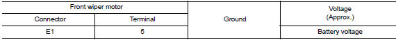
Is the inspection result normal? Yes >> replace front wiper motor. Refer to ww-62, "removal and installation".
No >> go to 2.
2. Check front wiper motor (auto stop) circuit continuity
- Turn the ignition switch OFF
- Disconnect ipdm e/r connector.
- Check continuity between ipdm e/r harness connector e46 and front wiper motor harness connector e1.

- Check continuity between ipdm e/r harness connector e46 and ground.
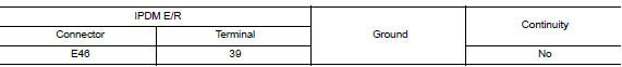
Is the inspection result normal? Yes >> replace ipdm e/r. Refer to pcs-30, "removal and installation" (with intelligent key system) or pcs-58, "removal and installation" (without intelligent key system).
No >> repair or replace the harness or connectors.
 Front wiper motor hi circuit
Component function check
1. Check front wiper hi operation
Ipdm e/r auto active test
Start ipdm e/r auto active test. Refer to ww-15, "diagnosis description"
(with intelligent key ...
 Front wiper motor ground circuit
Diagnosis procedure
Regarding Wiring Diagram information, refer to WW-24, "Wiring Diagram - With
Intelligent Key" or WW-29,
"Wiring Diagram - Without Intelligent Key".
1.Check ...
Other materials:
P2100, P2103 Throttle control motorrelay
DTC Logic
DTC DETECTION LOGIC
DTC No.
CONSULT screen terms
(Trouble diagnosis content)
DTC detecting condition
Possible cause
P2100
ETC MOT PWR-B1
(Throttle actuator “A”
control motor circuit/
open)
ECM detects a voltage of power source for
t ...
Steering column
Inspection
STEERING COLUMN ASSEMBLY
Check each part of steering column assembly for damage or
other malfunctions. Replace entire steering column
assembly if any parts are damaged.
Measure steering column rotating torque using Tool. Replace
steering column assembly if outside the ...
iPod®* player operation without Navigation System (if so equipped)
Connecting iPod®
WARNINGDo not connect, disconnect or operate the
USB device while driving. Doing so can be
a distraction. If distracted you could lose
control of your vehicle and cause an accident
or serious injury.
CAUTION
Do not force the USB device into the
U ...
