Nissan Sentra Service Manual: Front wheel hub
Exploded View
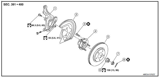
- Steering knuckle
- Splash guard
- Wheel stud
- Wheel hub and bearing
- Disc brake rotor
- Wheel hub lock nut
- Nut retainer
- Cotter pin
Removal and Installation
- Remove the wheel and tire using power tool. Refer to WT-47, "Exploded View".
- Remove the brake caliper torque member bolts, leaving the brake hose attached. Position the brake caliper aside with wire. Refer to BR-41, "BRAKE CALIPER ASSEMBLY : Removal and Installation".
CAUTION:
Do not depress the brake pedal while the brake caliper is removed.
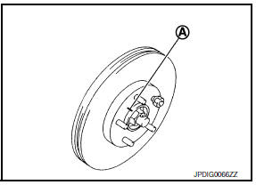
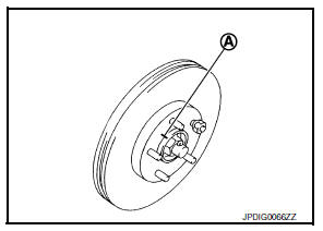
- Put alignment marks (A) on the disc brake rotor and on the wheel hub and bearing. Remove the disc brake rotor.
CAUTION:
Do not drop the disc brake rotor.
CAUTION:
Do not drop the disc brake rotor.
- Remove the wheel sensor bolt. Position the wheel sensor and the wheel sensor harness aside. Refer to BRC-106, "FRONT WHEEL SENSOR : Removal and Installation".
- Remove the cotter pin from the drive shaft.
- Remove the nut retainer from the wheel hub lock nut.
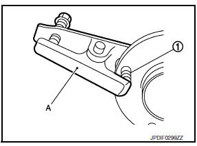
- Hold the wheel hub and bearing using Tool (A). Loosen the wheel hub lock nut.
Tool number (A): KV40104000 ( — )
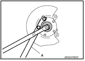
- Using a piece of wood and a suitable tool, tap on the wheel hub lock nut to disengage the drive shaft from the wheel hub and bearing.
CAUTION:
- Do not place the drive shaft joint at an extreme angle.
Also be careful not to overextend slide joint.
- Do not allow the drive shaft to hang down without support.
NOTE:
Use a suitable puller if the drive shaft cannot be separated from the wheel hub and bearing even after performing the above procedure.
- Remove the wheel hub lock nut.
- Remove the bolts and the wheel hub and bearing from the steering knuckle.
- Remove the splash guard from the steering knuckle.
- Suspend the drive shaft with suitable wire.
- If necessary, remove the wheel studs (1) from the wheel hub and bearing using a suitable tool (A).
CAUTION:
- Remove the wheel studs only when necessary.
- Do not hammer the wheel studs or damage to the wheel hub and bearing may occur.
- Pull out the wheel studs in a direction perpendicular to the wheel hub and bearing.
- Inspect the components. Refer to FAX-10, "Inspection".
INSTALLATION
Installation is in the reverse order of removal.
CAUTION:
- Do not reuse the wheel stud.
- Do not reuse the cotter pin.
- Place a washer (A) as shown to install the wheel studs (1) by using the tightening force of the nut (B).
CAUTION:
Check that there is no clearance between the wheel stud and the wheel hub and bearing.
- Clean the mating surfaces of the wheel hub lock nut and the wheel hub and bearing.
CAUTION:
- Do not apply lubricating oil to these mating surfaces.
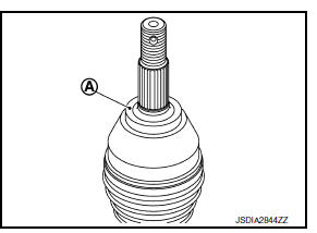
- Clean the mating surfaces of the joint sub-assembly and the wheel hub and bearing. Apply Molykote M77 lubricant to the surface (A) of the joint sub-assembly.
CAUTION:
Apply lubricant to cover the entire flat mating surface of the joint sub-assembly.
NOTE:
Always check with the Parts Department for the latest parts information.
Amount of lubricant : Refer to FAX-49, "Drive Shaft"
- Hold the wheel hub and bearing using Tool. Tighten the wheel hub lock nut.
CAUTION:
- Since the drive shaft is assembled by press-fitting, use a torque wrench to tighten the wheel hub lock nut. Do not use a power tool.
- Too much torque causes axle noise. Too little torque causes wheel bearing looseness. Tighten the wheel hub lock nut to the specification.
Tool number : KV40104000 ( — )
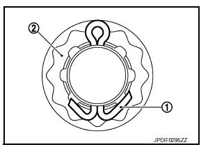
- When installing a the cotter pin (1) and the nut retainer (2), securely bend the cotter pin to prevent rattles.
- Align the matching marks (A) on the disc brake rotor and on the wheel hub and bearing.
- Complete the inspection. Refer to FAX-17, "Inspection".
Inspection
INSPECTION AFTER REMOVAL
Check the following items, and replace the part if necessary.
- Check components for deformation, cracks, and other damage.
- Check boots of transverse link and steering outer socket ball joint for breakage, axial end play, and swing torque.
- Transverse link: Refer to FSU-10, "Inspection".
- Steering outer socket: Refer to ST-8, "Inspection".
INSPECTION AFTER INSTALLATION
- Check the wheel sensor harness to be sure the connectors are fully seated.
- Check the wheel alignment. Refer to FSU-6, "Inspection".

 Front drive shaft boot
Exploded View
(LH)
Circular clip
Dust shield
Slide joint housing
Snap ring
Spider assembly
Boot band
Boot
Shaft
Damper band
Dynamic damper
Circular clip
Joint sub-assembly ...
Other materials:
Refrigeration system symptoms
Trouble diagnosis for unusual pressure
Diagnose using a manifold gauge whenever system’s high and/or low side
pressure(s) is/are unusual. The
marker above the gauge scale in the following tables indicates the standard
(usual) pressure range. Refer to
above table (Ambient air temperature ...
How to Check Terminal
CONNECTOR AND TERMINAL PIN KIT
Use the connector and terminal pin kits listed below when replacing
connectors or terminals.
The connector and terminal pin kits contain some of the most commonly
used NISSAN/INFINITI connectors
and terminals. For detailed connector and terminal pin repla ...
Help voice commands
The following voice commands can be spoken to
have the system provide instructions and tips for
using the NISSAN Voice Recognition system.
List Commands
What Can I Say?
General Help
Quit
Exit
Symptom/error message
Solution
The system responds “Command Not
Rec ...
