Nissan Sentra Service Manual: Front coil spring and strut
Exploded View
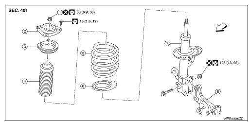
- Piston rod lock nut
- Strut mount insulator
- Strut mount bearing
- Bound bumper
- Coil spring
- Lower rubber seat
- Strut
- Steering knuckle
 Front
Front
Removal and Installation
REMOVAL
- Remove the wheel and tire using power tool. Refer to WT-47, "Exploded View".
- Remove the lock plate from the front coil spring and strut and reposition the brake hose. Refer to BR-25, "FRONT : Exploded View".
- Disconnect the stabilizer connecting rod from the front coil spring and strut. Refer to FSU-12, "Removal and Installation".
- Remove the wheel sensor bolt. Position the wheel sensor and the wheel sensor harness aside. Refer to BRC-106, "FRONT WHEEL SENSOR : Removal and Installation".
- Use a jack to support the transverse link and the steering knuckle.
- Remove the lower strut nuts and bolts (
 ).
).
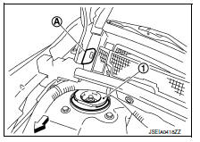
- Remove the grommet (A) from the cowl top cover.
 : Front
- Access 1 upper strut bolt through the grommet hole.
- Remove the upper strut bolts from the strut mount insulator (1).
- Remove the front coil spring and strut.
- Inspect the components. Refer to FSU-21, "Inspection".
INSTALLATION
Installation is in the reverse order of removal.
CAUTION:
Do not reuse piston rod lock nut or strut nuts.
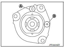
- Install the front coil spring and strut with the identification mark (A) of the strut mount insulator facing toward the front of the vehicle and the arrow (B) facing the outboard side.
NOTE:
The identification mark "0" shows the (RH) strut mount insulator and "1" shows the (LH).
- Perform the final tightening of the bolts and nuts under unladen conditions with the tires on level ground.
- Complete the inspection. Refer to FSU-21, "Inspection".
- After replacing the strut, always follow the disposal procedure to discard the old strut. Refer to FSU-22, "Disposal".

 Transverse link
Exploded View
Upper link
Front suspension member
Transverse link
Front
Removal and Installation
REMOVAL
Remove the wheel and tire using power tool. Refer to WT-47, "Explode ...
Other materials:
Front stabilizer
Exploded View
Stabilizer bar
Stabilizer clamp
Stabilizer bushing
Stabilizer connecting rod
Front coil spring and strut
Front suspension member
Front
Removal and Installation
REMOVAL
Remove the wheel and tire using power tool. Refer to WT-47, "Exploded
View".
...
P0138 HO2S2
DTC Logic
DTC DETECTION LOGIC
The heated oxygen sensor 2 has a much longer switching time between rich and
lean than the air fuel ratio (A/
F) sensor 1. The oxygen storage capacity of the three way catalyst (manifold)
causes the longer switching
time.
MALFUNCTION A
To judge the malfunction ...
Regulatory Information
FCC Regulatory information
CAUTION: To maintain compliance with
FCC’s RF exposure guidelines, use only the
supplied antenna. Unauthorized antenna,
modification, or attachments could damage
the transmitter and may violate FCC regulations.
Operation is subject to the following two cond ...
