Nissan Sentra Service Manual: ECU diagnosis information
BCM
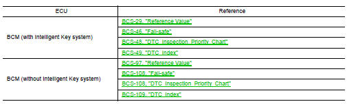
List of ECU Reference
 Diagnosis system (BCM) (without intelligent key system)
Common item
Common item : consult function (bcm - common item)
APPLICATION ITEM
CONSULT performs the following functions via CAN communication with BCM.
Direct Diagnostic Mode
Descriptio ...
 Wiring diagram
Tire pressure monitoring system
With intelligent key
WITH INTELLIGENT KEY : Wiring Diagram
Without intelligent key
WITHOUT INTELLIGENT KEY : Wiring Diagram
...
Other materials:
ECU diagnosis information
A/C AUTO AMP
Reference Value
VALUES ON THE DIAGNOSIS TOOL
TERMINAL LAYOUT
PHYSICAL VALUES
DTC Inspection Priority Chart
If some DTCs are displayed at the same time, perform inspections one by one
based on the following priority
chart.
DTC Index
*: Perform self ...
Precaution for Work
When removing or disassembling each component, be careful not to damage
or deform it. If a component
may be subject to interference, be sure to protect it with a shop cloth.
When removing (disengaging) components with a screwdriver or similar
tool, be sure to wrap the component
with a ...
Precaution for Supplemental Restraint System (SRS) "AIR BAG" and "SEAT BELT
PRE-TENSIONER"
The Supplemental Restraint System such as “AIR BAG” and “SEAT BELT
PRE-TENSIONER”, used along
with a front seat belt, helps to reduce the risk or severity of injury to the
driver and front passenger for certain
types of collision. Information necessary to service the system ...
