Nissan Sentra Service Manual: Ecu diagnosis information
Av control unit
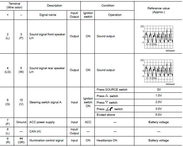
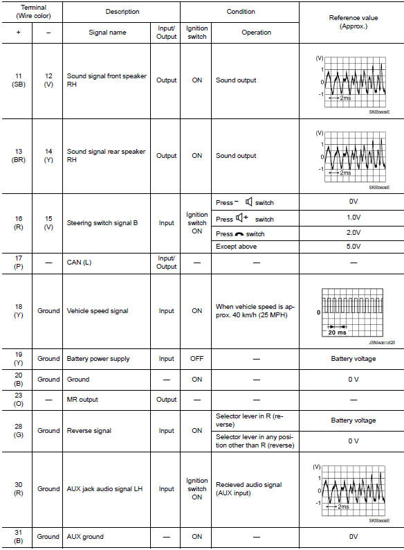
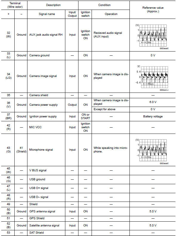
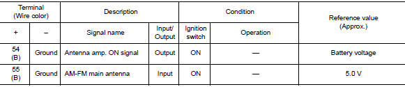
Reference value
TERMINAL LAYOUT

PHYSICAL VALUES
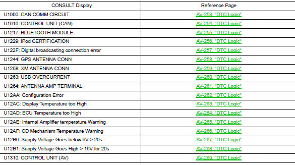
Dtc index
 System description
Component parts
Component parts location
Front tweeter lh
GPS antenna
Steering switches
Av control unit
Front tweeter rh
Microphone
Front door speaker LH
Front door speaker rh
...
 Wiring diagram
Navigation without bose
Wiring diagram
...
Other materials:
Precaution for Supplemental Restraint System (SRS) "AIR BAG" and "SEAT BELT
PRE-TENSIONER"
The Supplemental Restraint System such as “AIR BAG” and “SEAT BELT PRE-TENSIONER”,
used along
with a front seat belt, helps to reduce the risk or severity of injury to the
driver and front passenger for certain
types of collision. Information necessary to service the system ...
Diagnosis system (bcm) (with intelligent
key system)
Common item
Common item : consult function (bcm -
common item)
APPLICATION ITEM
CONSULT performs the following functions via CAN communication with BCM.
Direct Diagnostic Mode
Description
ECU identification
The BCM part number is displayed.
Self Diagnostic Result
...
Evap leak check
Inspection
CAUTION:
Do not use compressed air or a high pressure pump.
Do not exceed 4.12 kPa (0.042 kg/cm2, 0.6 psi) of pressure in EVAP
system.
NOTE:
Do not start engine.
Improper installation of EVAP service port adapter [commercial
service tool: (J-41413-OBD)] to the EVAP
...
