Nissan Sentra Service Manual: ECU diagnosis information
A/C AUTO AMP
Reference Value
TERMINAL LAYOUT

PHYSICAL VALUES
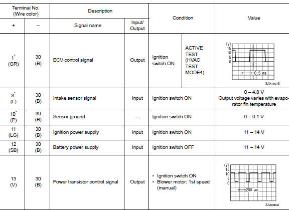
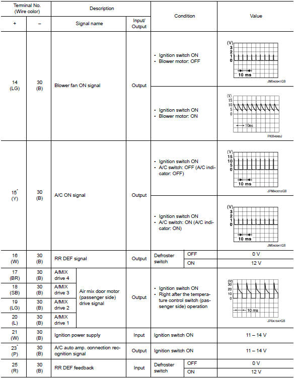
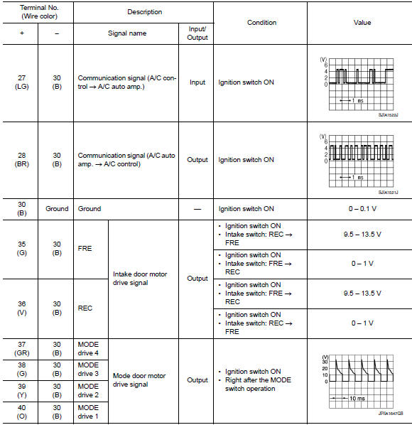
*:With manual A/C
ECM, IPDM E/R, BCM
List of ECU Reference

 System description
COMPONENT PARTS
Component Part Location
ECM
IPDM E/R
BCM (view with combination meter
removed)
A/C auto amp. (view with A/C switch
assembly removed)
A/C switch assembly
A/C ...
 Wiring diagram
Manual air conditioning system
Wiring Diagram
Manual heater system
Wiring Diagram
...
Other materials:
SRS Air bag warning lamp does not turn OFF
Diagnosis Procedure
1.CHECK AIR BAG MODULE AND SEAT BELT PRE-TENSIONER
Check the deployment of air bag module.
Is air bag module deployed?
YES >> Replace the malfunctioning parts.
NO >> GO TO 2.
2.CHECK AIR BAG FUSE
Check 10 A fuse [No.3, located in fuse block (J/B)].
Is th ...
1144 Incomplete steering angle sensor adjustment
DTC Logic
Dtc detection logic
Dtc
Display item
Malfunction detected condition
Possible causes
C1144
St ang sen signal
When neutral position adjustment of steering angle
sensor is not complete.
Harness or connector
Steering angle sensor
Abs actu ...
Multiport Fuel Injection System or Engine Control System
Before connecting or disconnecting any harness connector for the
multiport fuel injection system or ECM:
Turn ignition switch to “OFF” position.
Disconnect negative battery terminal.
Otherwise, there may be damage to ECM.
Before disconnecting pressurized fuel line from ...
