Nissan Sentra Service Manual: Component parts
Component Parts Location
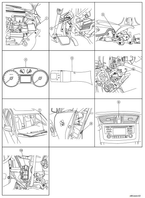
- IPDM E/R, (Headlamp high relay, Headlamp low relay, Taillamp relay and Front fog lamp relay (if equipped))
- Stop lamp switch
- Parking brake switch
- Combination meter
- Combination switch (lighting and turn signal switch)
- BCM (view with combination meter removed)
- Optical sensor
- Front door switch LH (Other doors similar)
- Hazard switch
- Daytime light relay (if equipped)
Component Description
| Part | Description |
| BCM | Controls the exterior lighting system. |
| Combination switch (Lighting & turn signal switch) | Refer to BCS-9, "COMBINATION SWITCH READING SYSTEM : System Description" (with Intelligent Key system) or BCS-80, "COMBINATION SWITCH READING SYSTEM : System Description" (without Intelligent Key system). |
| IPDM E/R | Controls the integrated relays and supplies voltage to the load according to the request from the BCM via CAN communication. |
| Stop lamp switch | Transmits power when the brake pedal is pressed to operate stop lamps. |
| Combination meter | Refer to MWI-8, "METER SYSTEM : System Description". |
| Daytime light relay (if equipped) | Sends power to the daytime lamp when operated by the IPDM E/R. |
| Front door switch LH/RH | Transmits the door open signal to the BCM. |
| Rear door switch LH/RH | |
| Optical sensor | Optical sensor converts the outside brightness (lux) to voltage and transmits the optical sensor signal to BCM to operate the autolight system. |
| Parking brake switch | Transmits the parking brake switch signal to the combination meter to operate the autolight system. |
| Hazard switch | Inputs the hazard switch signal to BCM. |

 System
Headlamp system
HEADLAMP SYSTEM : System Diagram
HEADLAMP SYSTEM : System Description
LOW BEAM OPERATION
When the lighting switch is in 2nd position, the BCM receives input
requesting the h ...
Other materials:
System
Warning chime system
Warning chime system : system diagram
Warning chime system : system description
Description
The buzzer for warning chime system is installed in the combination
meter.
The buzzer sounds when the combination meter receives a buzzer output
signal from the bcm.
Th ...
Dlc branch line circuit
Diagnosis procedure
1.Check connector
Turn the ignition switch off.
Disconnect the battery cable from the negative terminal.
Check the terminals and connectors of the data link connector for
damage, bend and loose connection
(connector side and harness side).
Is the inspection resul ...
Ecm branch line circuit
Diagnosis Procedure
1.Check connector
Turn the ignition switch off.
Disconnect the battery cable from the negative terminal.
Check the terminals and connectors of the ECM for damage, bend and loose
connection (unit side and
connector side).
Is the inspection result normal?
YES > ...
