Nissan Sentra Service Manual: Combination meter
Reference Value
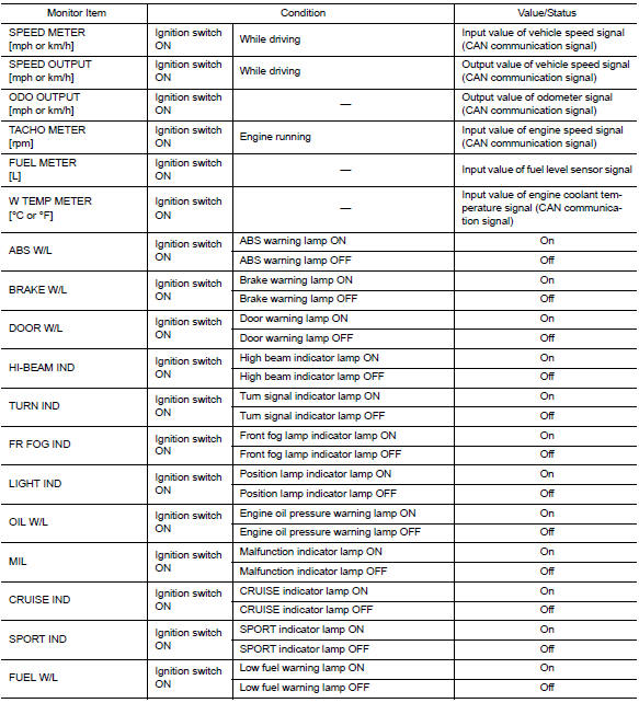
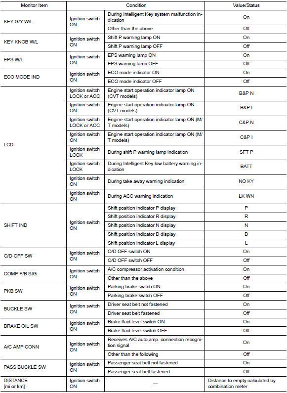
VALUES ON THE DIAGNOSIS TOOL
NOTE:
The following table includes information (items) inapplicable to this vehicle. For information (items) applicable to this vehicle, refer to CONSULT display items.

Note:
Some items are not available according to vehicle specification.
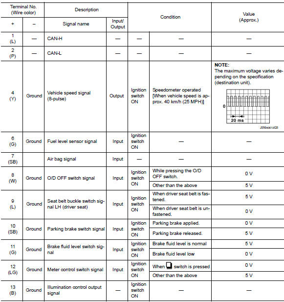
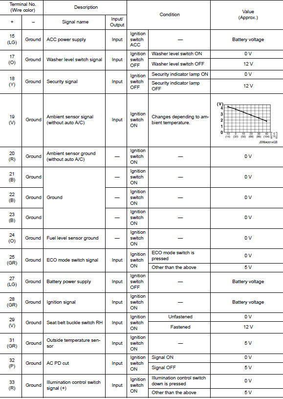
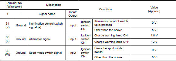
Terminal layout
Physical values
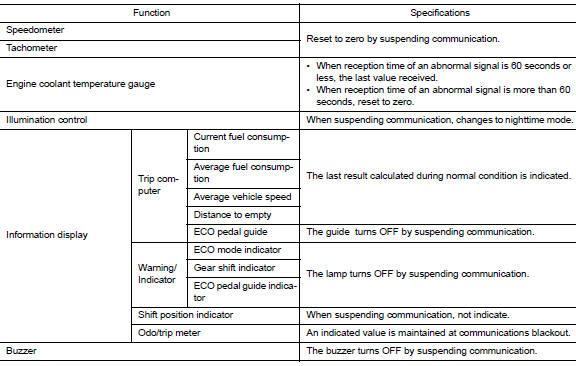
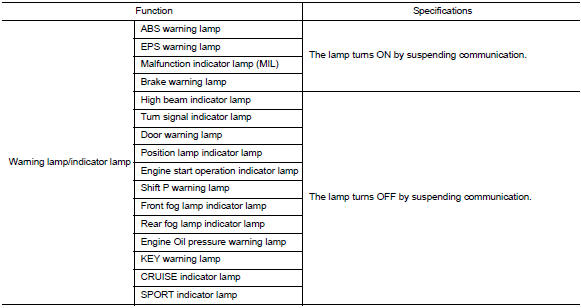
Fail-Safe
The combination meter activates the fail-safe control if can communication with each unit is malfunctioning.
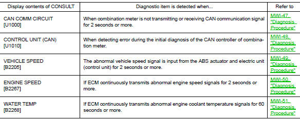
DTC Index

 Bcm (body control module)
List of ECU Reference
...
Other materials:
Intake manifold tuning system
INTAKE MANIFOLD TUNING SYSTEM : System
Description
SYSTEM DIAGRAM
SYSTEM DESCRIPTION
This system switches the length of intake air path according to the
low-to-medium speed range or high speed
range. Torque is increased in the low-to-medium speed range and the engine
output is improved ...
Exhaust gas (carbon monoxide)
WARNINGDo not breathe exhaust gases; they
contain colorless and odorless carbon
monoxide. Carbon monoxide is dangerous.
It can cause unconsciousness or
death.
If you suspect that exhaust fumes are
entering the vehicle, drive with all windows
fully open, and have ...
Precaution
Precaution for Supplemental Restraint System (SRS) "AIR BAG" and "SEAT
BELT PRE-TENSIONER"
The Supplemental Restraint System such as “AIR BAG” and “SEAT BELT PRE-TENSIONER”,
used along
with a front seat belt, helps to reduce the risk or severity of injur ...
