Nissan Sentra Service Manual: C1708, C1709, C1710, C1711 Transmitter (no data)
DTC Logic
NOTE:
The Signal Tech II Tool (J-50190) can be used to perform the following functions. Refer to the Signal Tech II User Guide for additional information.
- Activate and display TPMS transmitter IDs
- Display tire pressure reported by the TPMS transmitter
- Read TPMS DTCs
- Register TPMS transmitter IDs
DTC DETECTION LOGIC
| DTC | Display Item | Malfunction detected condition | Possible causes |
| C1708 | [NO DATA] FL | Tire pressure data signal from the front LH wheel transmitter cannot be detected. |
|
| C1709 | [NO DATA] FR | Tire pressure data signal from the front RH wheel transmitter cannot be detected. | |
| C1710 | [NO DATA] RR | Tire pressure data signal from the rear RH wheel transmitter cannot be detected. | |
| C1711 | [NO DATA] RL | Tire pressure data signal from the rear LH wheel transmitter cannot be detected. |
DTC CONFIRMATION PROCEDURE
1.PERFORM SELF DIAGNOSTIC RESULT
 With CONSULT
- Drive for 3 minutes at a speed of 40 km/h (25 MPH) or more, then drive normally for 10 minutes.
- Stop the vehicle.
- Perform đ▓đéĐÜSELF DIAGNOSTIC RESULTđ▓đéĐť.
Is DTC đ▓đéĐÜC1708đ▓đéĐť, đ▓đéĐÜC1709đ▓đéĐť, đ▓đéĐÜC1710đ▓đéĐť or đ▓đéĐÜC1711đ▓đéĐť detected? YES >> Proceed to WT-27, "Diagnosis Procedure".
NO >> Inspection End.
Diagnosis Procedure
NOTE:
The Signal Tech II Tool (J-50190) can be used to perform the following functions. Refer to the Signal Tech II User Guide for additional information.
- Activate and display TPMS transmitter IDs
- Display tire pressure reported by the TPMS transmitter
- Read TPMS DTCs
- Register TPMS transmitter IDs
Regarding Wiring Diagram information, refer to WT-15, "WITH INTELLIGENT KEY : Wiring Diagram" or WT- 18, "WITHOUT INTELLIGENT KEY : Wiring Diagram".
1.CHECK DATA MONITOR
 With CONSULT
- Drive for 3 minutes at a speed of 40 km/h (25 MPH) or more, then drive normally for 10 minutes.
- Stop the vehicle.
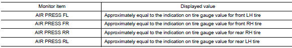
- On đ▓đéĐÜDATA MONITORđ▓đéĐť select đ▓đéĐÜAIR PRESS FLđ▓đéĐť, đ▓đéĐÜAIR PRESS FRđ▓đéĐť, đ▓đéĐÜAIR PRESS RRđ▓đéĐť and đ▓đéĐÜAIR PRESS RLđ▓đéĐť.
- Within 5 minutes after vehicle is stopped, read the values displayed on CONSULT
Are all tire pressures displayed 0 kPa (psi)? YES >> GO TO 2.
NO >> GO TO 5.
2.CHECK REMOTE KEYLESS ENTRY RECEIVER POWER CIRCUIT
Check voltage between remote keyless entry receiver connector and ground.
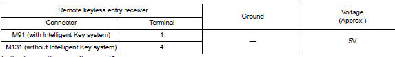
Is the inspection result normal?
YES >> GO TO 3.
NO >> Repair or replace harness or connectors.
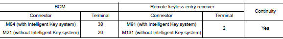
3.Check remote keyless entry receiver signal circuit
- Turn the ignition switch OFF.
- Disconnect BCM and remote keyless entry receiver connectors.
- Check continuity between BCM and remote keyless entry receiver connectors.
- Check continuity between BCM connector and ground.
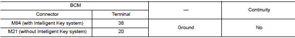
Is the inspection result normal? YES >> GO TO 4.
NO >> Repair or replace the malfunctioning harness or connector.
4.Check remote keyless entry receiver ground circuit
Check continuity between BCM and remote keyless entry receiver connectors.
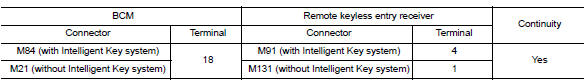
Is the inspection result normal? YES >> GO TO 5.
NO >> Repair or replace the malfunctioning harness or connector.
5.Transmitter id registration
Perform transmitter ID registration. Refer to WT-22, "Work Procedure".
Can the tire pressure sensor ID registration be completed? YES >> GO TO 6.
NO >> Replace applicable transmitter. Refer to WT-50, "Removal and Installation".
6.Check tire pressure signal
 With CONSULT
- Drive for 3 minutes at a speed of 40 km/h (25 MPH) or more, then drive normally for 10 minutes.
- Stop the vehicle.
- On đ▓đéĐÜDATA MONITORđ▓đéĐť select đ▓đéĐÜAIR PRESS FLđ▓đéĐť, đ▓đéĐÜAIR PRESS FRđ▓đéĐť, đ▓đéĐÜAIR PRESS RRđ▓đéĐť and đ▓đéĐÜAIR PRESS RLđ▓đéĐť.
- Within 5 minutes after vehicle stopped, check that the tire pressures are within specification. Refer to WT- 54, "Tire Air Pressure".
Is the inspection result normal? YES >> Inspection End.
NO >> Replace the BCM. Refer to BCS-73, "Removal and Installation" (with Intelligent Key system) or BCS-126, "Removal and Installation" (without Intelligent Key system).
 C1704, C1705, C1706, C1707 Low tire pressure
DTC Logic
NOTE:
The Signal Tech II Tool (J-50190) can be used to perform the following
functions. Refer to the Signal Tech II
User Guide for additional information.
Activate and display TPMS ...
 C1716, C1717, C1718, C1719 Transmitter (pressure data)
DTC Logic
NOTE:
The Signal Tech II Tool (J-50190) can be used to perform the following
functions. Refer to the Signal Tech II
User Guide for additional information.
Activate and display TPMS ...
Other materials:
Maintenance precautions
When performing any inspection or maintenance
work on your vehicle, always take care to prevent
serious accidental injury to yourself or damage to
the vehicle. The following are general precautions
which should be closely observed.
WARNING
Park the vehicle on a level surface, apply
...
Low tire pressure warning lamp
Component Function Check
1.CHECK THE ILLUMINATION OF THE LOW TIRE PRESSURE WARNING LAMP
Check that the low tire pressure warning lamp is turned OFF after
illuminating for approximately 1 second,
when the ignition switch is turned ON.
Is the inspection result normal?
YES >> Inspection ...
Bluetooth® Hands-Free Phone System voice commands
To access the Bluetooth® Hands-Free Phone
System voice commands:
Press the button.
Say ÔÇťCallÔÇŁ and then a name in the vehicle
phonebook to call that entry. Otherwise, say
ÔÇťPhoneÔÇŁ to access various phone commands.
If the Bluetooth┬« has been set to ÔÇťOffÔÇŁ, the
system announ ...
