Nissan Sentra Service Manual: C1109 Power and ground system
DTC Logic
DTC DETECTION LOGIC
| DTC | Display Item | Malfunction detected condition | Possible causes |
| C1109 | BATTERY VOLTAGE [ABNORMAL] |
|
|
DTC CONFIRMATION PROCEDURE
1.CHECK SELF DIAGNOSTIC RESULT
 With CONSULT.
-
Turn the ignition switch ON.
-
Perform self diagnostic result.
Is DTC C1109 detected? YES >> Proceed to diagnosis procedure. Refer to BRC-62, "Diagnosis Procedure".
NO >> Inspection End.
Diagnosis Procedure
Regarding Wiring Diagram information, refer to BRC-44, "Wiring Diagram".
1.Connector inspection
-
Turn ignition switch OFF.
-
Disconnect abs actuator and electric unit (control unit) connectors.
-
Check connectors and terminals for deformation, disconnection, looseness or damage.
Is the inspection result normal? Yes >> go to 2
No >> repair or replace as necessary.
2.Check abs actuator and electric unit (control unit) ignition power supply circuit
Check voltage between abs actuator and electric unit (control unit) connector e33 terminal 28 and ground.
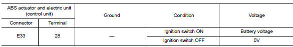
Is the inspection result normal? Yes >> go to 3
No >> repair or replace malfunctioning components.
3.Check abs actuator and electric unit (control unit) ground circuit
Turn ignition switch OFF.
Check continuity between abs actuator and electric unit (control unit) connector e33 terminals 13, 38 and ground.
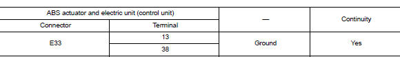
Is the inspection result normal? YES >> Replace ABS actuator and electric unit (control unit). Refer to BRC-110, "Removal and Installation".
NO >> Repair or replace malfunctioning components.
 C1105, C1106, C1107, C1108 Wheel sensor
Description
When the sensor rotor rotates, the magnetic field changes. It
converts the magnetic field changes to current
signals (rectangular wave) and transmits them to the ABS actuator and elec ...
 1110, C1170 ABS Actuator and electric unit (control unit)
DTC Logic
DTC DETECTION LOGIC
DTC
Display item
Malfunction detected condition
Possible cause
C1110
CONTROLLER FAILURE
When there is an internal malfunction in the ABS ...
Other materials:
Dtc/circuit diagnosis
Power supply and ground circuit
Diagnosis Procedure
Refer to LAN-7, "CAN COMMUNICATION SYSTEM : System Description".
Vehicle security indicator
Description
DTC DETECTION LOGIC
NOTE:
U1000 can be set if a module harness was disconnected and reconnected,
perhaps during a repair. Con ...
Cooler pipe and hose
Exploded view
High-pressure service port
High-pressure pipe
Expansion valve
Low-pressure service port
Low-pressure flexible hose
Compressor
Refrigerant pressure sensor
Condenser and liquid tank assembly
High-pressure flexible hose
Low-pressure flexible hose
Low-pressure f ...
Strg branch line circuit
Diagnosis procedure
1.Check connector
Turn the ignition switch OFF.
Disconnect the battery cable from the negative terminal.
Check the terminals and connectors of the steering angle sensor for
damage, bend and loose connection
(unit side and connector side).
Is the inspection result ...
