Nissan Sentra Service Manual: B0094 Crash zone sensor
Description
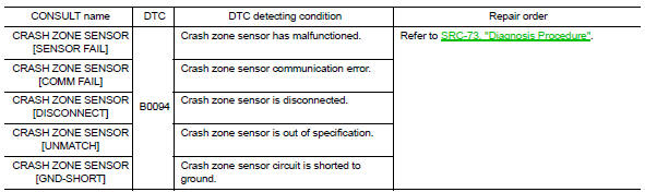
DTC B0094 CRASH ZONE SENSOR
The crash zone sensor is wired to the air bag diagnosis sensor unit. The air bag diagnosis sensor unit will monitor for opens and shorts in detected lines to the crash zone sensor.
PART LOCATION
Refer to SRC-5, "Component Parts Location".
DTC Logic
DTC DETECTION LOGIC
With CONSULT
DTC CONFIRMATION PROCEDURE (With CONSULT)
1.CHECK SELF-DIAG RESULT
- Turn ignition switch ON.
- Check for DTC using CONSULT.
Is the DTC detected? YES (Current DTC)>>Refer to SRC-73, "Diagnosis Procedure".
YES (Past DTC)>>GO TO 2.
NO >> Inspection End.
2.ERASE SELF-DIAG RESULT
Erase the DTC using CONSULT.
Can the DTC be erased? YES >> Inspection End.
NO >> Refer to SRC-73, "Diagnosis Procedure".
DTC CONFIRMATION PROCEDURE (Without CONSULT)
1.CHECK SELF-DIAG RESULT
- Turn ignition switch ON.
- Check the air bag warning lamp status. Refer to SRC-17, "Trouble Diagnosis without CONSULT".
NOTE:
SRS will not enter diagnosis mode if no malfunction is detected in user mode.
Is the DTC detected? YES >> Refer to SRC-73, "Diagnosis Procedure".
NO >> Inspection End.
Diagnosis Procedure
1.HARNESS CONNECTOR
Visually inspect all applicable harness connectors for the following:
- Visible damage to connector or terminal
- Loose terminal
- Poor connection
NOTE:
All harness connectors should be inspected from the air bag diagnosis sensor unit to the end component (including any in-line connectors).
Is the inspection result normal? YES >> GO TO 2.
NO >> Perform one of the following repairs:
- Visible damage: Replace the harness
- Loose terminal: Secure the terminal.
- Poor connection: Secure the connection.
2.CONFIRM DTC
- Reconnect all harness connectors.
- Turn ignition switch ON.
- Check for DTC using CONSULT.
Is DTC still current? YES >> GO TO 3.
NO >> Refer to GI-39, "Intermittent Incident".
3.WIRING HARNESS
Check the wiring harness for visible damage.
NOTE:
The entire wiring harness should be inspected from the air bag diagnosis sensor unit to the end component (including any in-line connectors).
Is the inspection result normal? YES >> GO TO 4.
NO >> Replace the harness.
4.CONFIRM DTC
- Reconnect all harness connectors.
- Turn ignition switch ON.
- Check for DTC using CONSULT.
Is DTC still current? YES >> GO TO 5.
NO >> Refer to GI-39, "Intermittent Incident".
5.CRASH ZONE SENSOR
- Replace the crash zone sensor. Refer to SR-25, "Removal and Installation".
- Turn ignition switch ON.
- Check for DTC using CONSULT.
Is DTC still current? YES >> GO TO 6.
NO >> Clear DTC. Inspection End.
6.AIR BAG DIAGNOSIS SENSOR UNIT
- Replace the air bag diagnosis sensor unit. Refer to SR-28, "Removal and Installation".
- Turn ignition switch ON.
- Check for DTC using CONSULT.
Is DTC still current? YES >> GO TO 7.
NO >> Clear DTC. Inspection End.
7.RELATED HARNESS
Replace the related harness.
>> END
 B0093 FRont door satellite sensor LH
Description
DTC B0093 FRONT DOOR SATELLITE SENSOR LH
The front door satellite sensor LH is wired to the air bag diagnosis sensor
unit. The air bag diagnosis sensor
unit will monitor the front do ...
 B0096 Front side air bag satellite sensor RH
Description
DTC B0096 FRONT SATELLITE SENSOR RH
The front side air bag satellite sensor RH is wired to the air bag diagnosis
sensor unit. The air bag diagnosis
sensor unit will monitor the front ...
Other materials:
Ground
Ground distribution
Main harness
Engine room harness
Engine control harness
Body harness
...
Rear bumper
Exploded view
Rear bumper side bracket (LH)
Rear bumper reinforcement
Rear bumper energy absorber
Rear bumper fascia reflector (LH)
Rear bumper fascia reflector (RH)
Rear bumper fascia
Rear bumper side bracket (RH)
Pawl
Removal and installation
CAUTION:
Bumper fascia is ma ...
Wiring diagram
Remote keyless entry system
Wiring diagram
Power door lock system
Wiring Diagram
Trunk lid opener
Wiring diagram
...
